 Synchrotron Utilization Section
Frontend Control & Interlocking System
Frontend is an interface between synchrotron radiation (SR) source and a beamline. The main functions of the frontend are a) to protect the storage ring vacuum from any downstream vacuum failure in the beamline b) to protect the beamline components from high power synchrotron radiation of undulator c) to ensure the personnel safety of user, d) to define synchrotron radiation (SR) beam, and e) to provide SR beam diagnostics.
The design of a frontend depends mainly upon the source and also on the beamline to some extent. Indus-2 frontends are different for each source type like bending magnet, undulator and beamlines like hard x-rays, soft x-rays. Fig. 1 shows the undulator frontend layout at 0° port of bending magnet.
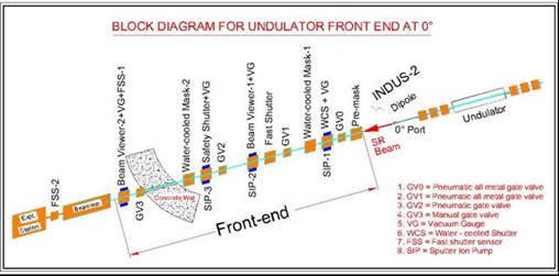
Figure 1: Block diagram of Undulator Frontend at 0° port of bending magnet
The frontend control and interlock system (FEC&IS) for bending magnet frontends is VME based with LabVIEW used for graphical user interfaces. The FEC&IS for undulator frontends is based on PLC with SCADA software. However, the operational design of both bending magnet frontends and undulator frontends is similar.
FRONTEND CONTROL ARCHITECTURE
Most of the frontend components are inside the shielding wall and are not accessible during the machine operation. One of the major considerations for the design of control and interlock scheme was to provide remote operation and monitoring of all frontend signals from respective frontend control station (FCS) at beamline and also from the centralized frontend control system (CFCS). A frontend acts as an interface between SR source and a beamline, design of fail-safe and redundant interlocking scheme is very important to protect machine vacuum, beamline components and for user safety.
The undulator frontend control and interlock system (FEC&IS) is based on PLC with Ethernet communication interface. The control architecture of undulator FEC&IS is shown in fig. 2.
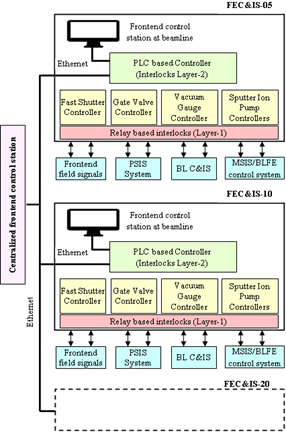
Figure 2: Control architecture of undulator FEC&IS
|
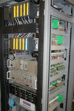
Figure 3: FEC&IS rack
|
To increase the reliability of system, two levels of interlocks are implemented. At layer-1, relay based interlocks are implemented for critical signals like machine protection, beamline component protection and user safety. A complete set of interlocks are implemented in PLC at layer-2 which includes critical signal interlocks and interlocks to ensure the sequenced operation of the frontend valves.
The sputter Ion Pump (SIP) controllers of all frontends are connected on a separate LAN for monitoring and data logging. Presently, 110 number of SIP controllers are working round the clock on 19 operational frontends.
FEC&IS has been integrated with MSIS, BLC&IS and PSIS by using potential free normally open contacts. Many of the status and beam permission signals are shared among these systems and are interlocked for the safe operation of the machine, frontend and beamline.
A commercially available SCADA software (WinCC) is used to develop graphical user interfaces for FEC&IS. The CFCS is designed to have an integrated monitoring and control of all the undulator frontends from single desktop PC. Major features implemented at CFCS are data monitoring, remote operation, event-based and continuous data logging, alarms, online and historical data trends and user authentication & authorisation. Status of all interlocks along with control of different gate valves is provided in the “Operation” screen as shown in fig. 4.
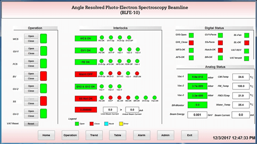
Figure 4: Operation screen of ARPES beamline frontend
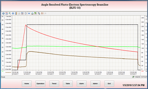
Figure 5: Vacuum conditioning of frontend with SR beam
Figure 5 shows the data trend of Vacuum conditioning of the frontend with SR beam. Figure 6 shows the graphical user interface of bending magnet frontend, developed in LabVIEW.
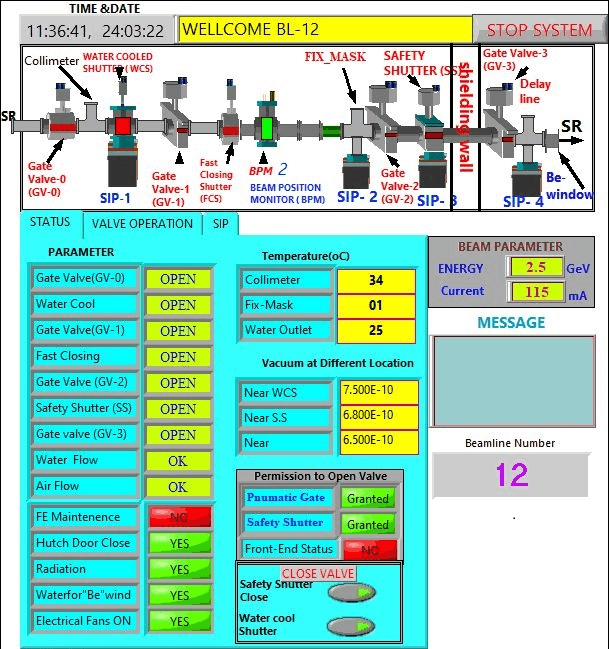
Figure 6: graphical user interface of bending magnet frontend, developed in LabVIEW
|


