 Synchrotron Utilization Section
Beamline Control & Interlocking System
The synchrotron radiation (SR) produced from electron storage ring is conditioned and optimized as per the needs of the experiments and transported to the experimental station through beamlines. Beamlines can be classified as (1) based on energy – Soft X-ray beamline or Hard X-ray beamline, (2) based on SR source – Bending magnet or Insertion device (Undulator), (3) based on the experimental techniques. Each beamline has a unique optical design, however many mechanical and electrical components are common across the beamlines. Beamline components can be grouped into:
- Optics – Mirrors, Monochromators, Slits
- Vacuum System – Vacuum pumps, Vacuum gauges, Gate valves
- Diagnostic devices – Scanning wire monitors, beam viewers
- Experimental station
Based on the control functionality, beamline control systems are grouped into following systems:
- Beamline control and interlocking system
- Personnel safety system (Search and Secure system)
- Motion control systems
- Undulator control system
- Front-end control system
- Data acquisition systems for user experiments
BEAMLINE CONTROL ARCHITECTURE
Most of the frontend components are inside the shielding wall and are not accessible during the machine operation. One of the major considerations for the design of control and interlock scheme was to provide remote operation and monitoring of all frontend signals from respective frontend control station (FCS) at beamline and also from the centralized frontend control system (CFCS). A frontend acts as an interface between SR source and a beamline, design of fail-safe and redundant interlocking scheme is very important to protect machine vacuum, beamline components and for user safety.
The undulator frontend control and interlock system (FEC&IS) is based on PLC with Ethernet communication interface. The control architecture of undulator FEC&IS is shown in fig. 2.
As a typical case, the beamline control layout for XMCD beamline at Undulator port of Indus-2 is shown in figure1. The beamline control and interlocking system design is uniform across the beamlines however number of signals varies depending on type of beamline. The control system generates two integrated signals - Beamline READY and Beamline Vacuum OK which further are interlocked with front-end operation. This ensures that front-end vacuum valve and safety shutter can be opened only if all the downstream beamline components are in safe state.
Table 1 gives the list of beamlines where BCIL has implemented beamline control systems.
Figure 2 shows the HMI panel of ARPES beamline control system and figure 3 shows the HMI panel of EXAFS beamline Ionisation chamber gas filling system.
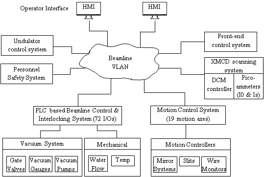
Figure 1: XMCD beamline control layout
Table 1
| Sr. No. | Name of beamline |
| 01 | Soft x-ray absorption spectroscopy (SXAS) beamline at BL-01 port |
| 02 | Engineering Applications beamline at BL-02 port |
| 03 | Soft x-ray reflectivity beamline at BL-03 port |
| 04 | X-ray lithography beamline BL-07 port |
| 05 | Extended X-ray absorption fine-structure beamline BL-09 port |
| 06 | Angle resolved photoelectron spectroscopy beamline BL-10 port |
| 07 | Angle Dispersive X-Ray Diffraction beamline BL-12 port |
| 08 | Microprobe X-ray fluorescence beamlineBL-16 port |
| 09 | X-ray Magnetic Circular Dichroism beamline BL-20 port |
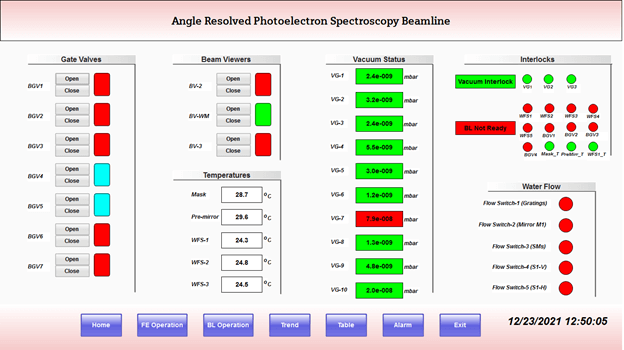
Figure 2: HMI panel of ARPES beamline control system
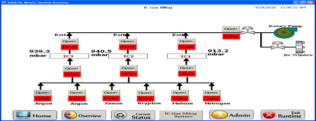
Figure 3: HMI panel of EXAFS beamline Ionisation chamber gas filling system
|


