| Accelerator Ramping Power Converter Section (ARPCS) |
 Accelerator Ramping Power Converter Section (ARPCS)
1.Team Members
Accelerator Ramping Power Converter Section (ARPCS)
1.Team Members
Present team members are as follows:
- Shri Manoj Leelachand Gandhi
- Smt Seema Singhai Sheth
- Ms Aradhana Kumari
- Shri Ujjwal Yadav
- Shri Bonagiri Bhanuprakash
- Shri Anil Kumar
- Shri Lalit Biranwar
- Shri Kandipalli Gopi
- Shri Brijesh Kumar Mishra
- Shri Vinay Kumar Rajaram Maurya
- Shri Surya Prakash Sah
Other important team members who have contributed in the works described in this section are:
- Shri A. C. Thakurta
- Shri A. P. Thipsay
- Shri Harish Kumar Khatwani
- Shri Shesh Nath Singh
- Shri V. D. Sharma
- Shri Tribhuwan Singh
- Shri Vaddadi Ramesh
- Shri Ramesh Prasad
2.Activities pursued in Accelerator Ramping Power Converter Section
- 2.1. Design and development of power supplies for Transport Line-3 Quadrupole Magnets
- 2.2. Design and development of Active Shunts for Indus-2 Quadrupole Magnets
- 2.3. Design and development of Pulsed Power Supply for Electron Gun
- 2.4. Design and development of Bipolar Power Supply for Variable Pole Gap Magnet
- 2.5. Design and development of Line-side Active Harmonic Filter
- 2.6. Design and development of Booster Quadrupole Magnet Adjustment Coil Power Supplies
- 2.7. Digital Control of a Zero Voltage Switching Power Supply
- 2.8. Design and development of DSP based supervisory control for the power supplies of Transport Line -1, Transport Line -2 and SR Indus-1
- 2.9. Installation of Smoke Exhaust System for Indus-2 Experimental Hall
- 2.10. Installation and maintenance of Fire Alarm and Detection System of Indus Accelerator Complex
- 2.11. Installation of Public Address system in Indus Complex
- 2.12. Design and development of Power Supply for Indus-2 Dipole Magnets
- 2.13. Design and development of Power Supplies for Booster Horizontal Steering Coils
- 2.14. Design and development of Field Mapping Power Supply
- 2.15. Design and development of Power Supplies for Fast corrector Magnets of Indus-2
- 2.16. Design and development of High Stability power supply
- 2.17. Design and Development of SCADA System for Remote Control and monitoring of Vacuum Furnace
- 2.18. Design and development of Auto Transfer Switch (ATS) for emergency and critical loads of Indus Complex.
- 2.19. Design and development of digitally controlled PWM Rectifier for harmonic reduction and bidirectional power flow
- 2.20. Design and development of FPGA based digitally controlled power supply for Magnet Testing
- 2.21. Design and assembly of Wave-Length Shifter DC Power Supply (135A/150V, ±50 ppm)
3.Detailed Work Description
- 3.1. Design and development of power supplies for Transport Line-3 Quadrupole Magnets
Features
- Current controlled power supply
- Regulation against - line and load variations
- High Stability - Lower temperature drift and ripple
- ZVS throughout the load range
- Active damping of LC filter
- High frequency transformer primary volt-sec balance
- Reduced Switching losses and EMI
- Water Cooling of power devices and major circuit components
Specifications:
- Maximum current: 180 A at 45 V
- Stability: ± 500 PPM
- Load: L = 56 mH, R = 0.25 ohm
|
|
SCR Pre-regulator |
Zero-Voltage-Switching IGBT Inverter |
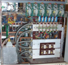
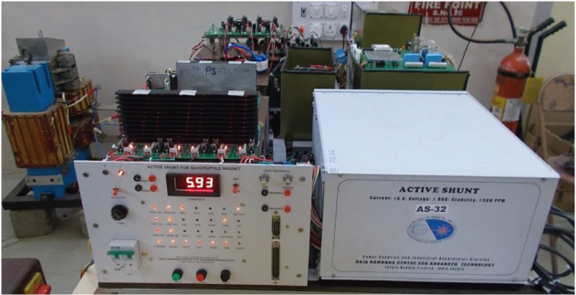
- 3.2.Design and development of Active Shunts for Indus-2 Quadrupole Magnets
Features
- Bipolar current adjustment
- Stability much better than ±500 PPM
- Very low DC sensitivity to load-source disturbance
- Utility interface supports bidirectional power flow
- Near unity power factor operation in all quadrants
- Low line-side current THD
- Isolation of load when not in operation
- Soft start and stop
Specifications:
- Load voltage : ± 80 V
- Load current : ± 6 A
- Stability on flat portion : better than ± 500 PPM
|
Active Shunt on a Test Bench |
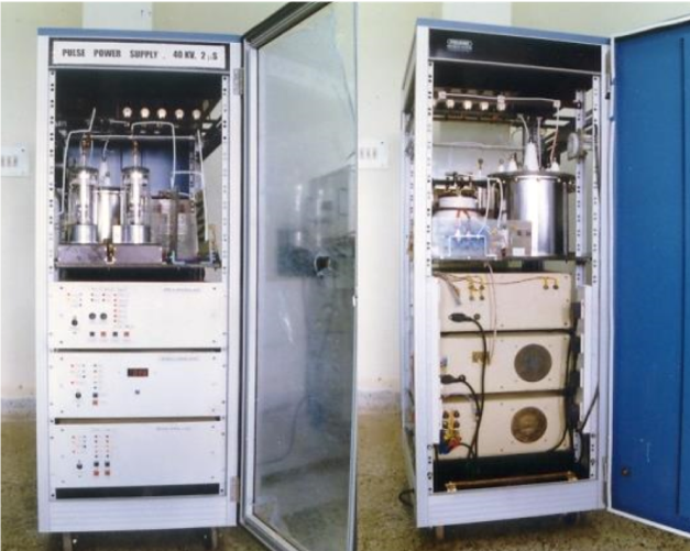
- 3.3 Design and development of Pulsed Power Supply for Electron Gun
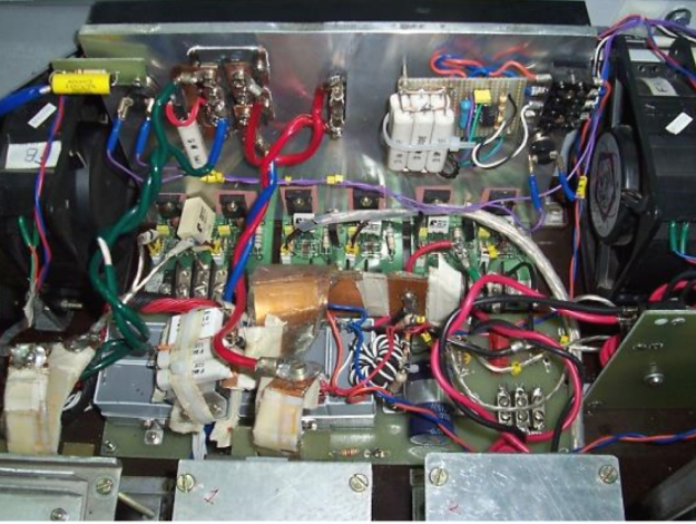
The scheme uses a doubly tuned circuit and two thyratrons. In the implemented scheme, the maximum working voltage is equal to the load voltage reducing the safety requirements (as compared to PFN). Less number of components, simpler tuning, lower working voltage and hence the associated benefits in device and component ratings make this scheme attractive at the expense of loss of efficiency. There are three stages of the power supply. An AC to DC converter and then a doubly tuned circuit follow a switching circuit. The diode electron gun is coupled to the high voltage power supply through an oil immersed pulse transformer having ratio 1:5. The balanced arrangement of high voltage application to the gun offers minimum stray capacitive coupling to the earth via the filament transformer improving rise and fall times of the pulse.
Specifications:
- Voltage - 40 kV
- Current - 0.5 A
- Pulse Width - 2 μs
- Rise and fall times < 325 ns
- Pulse Top Flatness < 5 %
- Repetition Rate - 1 Hz
- Load - Electron Gun
|
Electron gun pulser used in PWT Linac development and testing in Beam Physics & Free Electron Laboratory |
- 3.4. Design and Development of Bipolar Power Supply for Variable Pole Gap Magnet
The power supply has a single-phase diode rectifier with an LC filter at its front end followed by a half-bridge switch mode converter. The half-bridge converter, operating at 50 kHz, has full-bridge rectifier configuration at the output with an LC filter. A four-quadrant power converter based on Unipolar switching scheme is employed at the output stage. The scheme provides: 1) true bipolar output current with minimum switching ripple at lower amplitudes of load current, and 2) the voltage ripple frequency at twice the switching frequency reducing output filter size. The H-bridge switches at 50 kHz. The load current is sensed with a low temperature coefficient Zeranin shunt.
Specifications:
- Maximum DC load current ±15 A
- Maximum DC load voltage ±50 V
- Full scale stability ±100 PPM
- Full scale ripple ±100 PPM
- Inductive load time constant 0.66 - 2 s
- Maximum load current di/dt 1 A/s
|
Bipolar Power Supply for Variable Pole Gap Magnet |
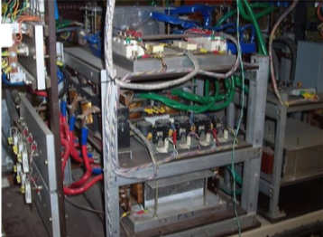
- 3.5. Design and development of line-side Active Harmonic Filter
A shunt filter topology using three phase IGBT Inverter is used. The active filter is connected to a harmonic producing load in parallel through coupling chokes. The filter capacitor is charged to dc voltage by operating the inverter bridge in rectification mode simultaneously. Due care is needed to be taken to control inrush current at the start up. The control scheme is such that the filter not only corrects the current harmonics but compensates reactive power thus improving overall power factor of the system.
Specifications:
- Three phase VSI Rating: 5 kVA
- Load: TL-3 Quadrupole Magnet power supply having six-pulse SCR converter at its input.
|
Active Harmonic Filter: Three Phase IGBT Switching Bridge |
- 3.6. Design and development of Booster Quadrupole Magnet Adjustment Coil Power Supply
This current regulated power supply tracks a ramped current reference. Quadrupole magnet is magnetically coupled with dipole magnet. Under the excitation of ramping current through Dipole and Quadrupole magnets, power supply is required to take care of mutually and self-induced step voltages. To meet the step changing voltage requirements at the output, feed-forward control has been incorporated in the power supply. Load and line regulation are taken care by the fast voltage control loop whereas slow current loop tracks the current reference.
Specifications:
- 180 A, 50 V
- Stability 500 PPM
- Load Magnet (L - R)
|
Booster Quadrupole Magnet Adjustment Coil Power Supplies |
- 3.7. Digital Control of a Zero Voltage Switching Power Supply
Control Objectives:
- Proper SCR firing angle control to avoid inrush current through the capacitor bank of the AC-DC converter at start-up
- Output (dc bus) voltage regulation of the AC-DC converter
- Active damping of L-C filter at the output of the AC-DC converter
- Blocking of dc current through primary winding of the transformer used in the H-Bridge high frequency inverter
- Active damping of L-C filter at the output stage of the DC-DC converter
- Fast voltage loop control for the better rejection of input disturbances
- A slow load current loop to track the current reference
- Digital Implementation
Hardware Interfacing:
- Control Software
- Generation SCR Firing Pulses and Manipulation of Firing Angle, and
- Generation of Phase-Shifted PWM Signals for IGBTs
Specifications:
- Maximum current: 155 A at 19 V
- Stability: ± 500 PPM
- Load: L = 27 mH, R = 0.12 Ohm
|
TMS320F2812 Controlled Current Regulated ZVS power supply (TL-3 QPM Spare) |
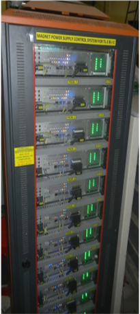
- 3.8. Design and development of DSP based supervisory control for the power supplies of Transport Line -1, Transport Line -2 and SR Indus-1 (Work carried out by Smt Seema Singhai Sheth at ACSD)
The supervisory control system for the Magnet Power Supplies of three sectors, namely, Transport Line -1, Transport Line -2 and Indus-1 SR are based on distributed control architecture. In this scheme each power supply is connected to a Digital Signal Processor (DSP) based controller sitting in its vicinity. All the controllers pertaining to one sector communicates to a master server on a common serial link, RS485 with a custom protocol. These controllers have high speed response and high accuracy. The controllers are very compact (in 19” width, 2U height form factor).
Functions and features of the control system:
- Digital control of seven parameters through potential free contacts.
- Status monitoring of seven parameters through optically isolated digital inputs.
- Setting and reading of the controller configuration.
- Analog reference generation of any arbitrary shape required for generating reference profiles for setting power supply current.
- Analog reference has accuracy better than 0.01% and stability better than 100 PPM.
- Readback of actual current of the supply and the set reference with accuracy better than 0.01% at 10 kHz sampling rate.
- Facilitate synchronized data capture following an external clock or events (for post-mortem analysis).
|
DSP based Control for magnet power supplies of TL-1, TL-2 and SR I-1 (Seema Singhai Sheth at ACSD) |
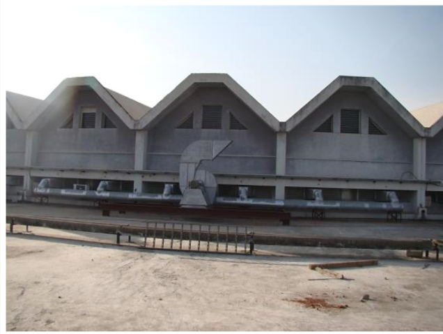
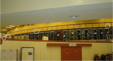
- 3.9. Installation of Smoke Exhaust System for Indus-2 Experimental Hall
A smoke exhaust system as per NFPA-92 standard has been installed in the Indus-2 experimental hall so that the safety of the personnel working in these areas is ensured in the event of fire and the loss of property can be minimized. The area of the hall has been divided into 16 zones covering 48 sectors. Each zone has a blower of 10000 m3/h capacity which receives smoke from a duct connected to six suction openings. There are thirteen direct driven blowers and three belt driven blowers which cater to the requirement of six air changes per hour as per the guidelines of CFPA-E.
|
Smoke exhaust system covering three sectors of a zone with a direct driven blower; Smoke exhaust system covers 16 zone of Indus experimental hall. |
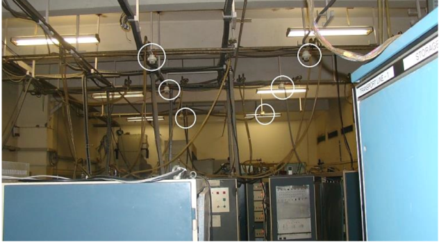
- 3.10.Installation and maintenance Fire Alarm and Detection System of Indus Accelerator Complex
A new 4th generation 100% hot redundant, intelligent addressable fire alarm and detection system of Schrack make has been installed in Indus Complex. The system uses multiple detectors in a loop and these are characterized by application algorithm. The new fire alarm and detection system consists of 3 control panels; each panel can have 10 loops. Each loop can accommodate maximum 127 numbers of devices. In presently configured system, each panel uses four loops. In all 1100 devices, like multi-criteria detectors (photoelectric smoke detector and heat detector), manual call points, panel mounted detectors, trench detectors, beam detectors, solar blind flame detectors, ventilation duct detectors, loop powered sounders, monitor modules, flashers, aspirating smoke detectors, etc., have been connected to the control panel through 10 loops. The system has 3 control panels, 5 Synoptic panels, and a colour Graphical User Interfaces software (GUI) installed at different locations including control room. All the three control panels, the virtual map and the synoptic panels are networked together, which facilitates us to know the status of the fire alarm system. All the devices in the system have inbuilt short circuit protection. This system has been installed as per NFPA 72-2016.
|
Installation of 4th generation Fire Alarm and Detector system in Indus accelerator complex. Pictures depict detectors, control panel and synoptic panel |
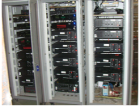
- 3.11.Installation of Public Address System in Indus Complex
PA system has been upgraded with paging mikes, priority controller, speaker loop line detector, power sequencer, audio splitter, audio amplifiers, one way and dual way projection speakers, wall speakers, column speakers, etc. Two Groups (A and B) catering the need of 14 zones spread over the entire Indus complex, based on the background noise ranging from 50 dBm to 88 dBm during machine operation, were defined to decide the exact power requirement of the amplifiers. Announcement can be made through telephones for Group-A, Group-B or for both. An emergency microphone kept in the control room has the highest priority. It is also possible to make announcements using telephone lines and two paging microphones located at the security posts. Provision for making recorded announcements from the control room has also been given. Speaker loop detectors have been placed for easy detection of faults in speaker circuits. The system has a controller to decide priority of the input audio signals. One way projection speakers are being used in 7 meter high experimental hall. Dual projection speaker are used in 2 to 3 meter wide corridors and wall speaker used in laboratories.
|
|
Components of the newly installed and commissioned Public Address System in Indus-2 Accelerator Complex |
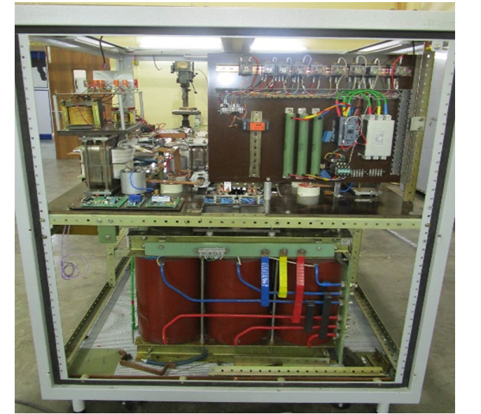
- 3.12. Design and development of Power Supply for Indus-2 Dipole Magnets
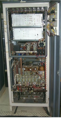
Seventeen dipole magnets, sixteen in Indus-2 ring and a reference dipole magnet in PS hall, are connected in series. All these magnets are energised by a single power supply. For this load, a 12-pulse thyristorized converter is used which operates in voltage control mode. The stringent stability specification of ±50 PPM is met by series pass regulator cascaded with the 12-pulse converter. The use of this series pass element allows higher control loop bandwidth compared to the SCR Bridge. The 12-pulse converter and Transistorised series pass regulator operate in series to supply regulated current to load.
Features:
- Current Controlled power supply
- High load current long term stability (± 50 PPM)
- 6-pulse SCR controlled pre regulator followed by Transistorised series pass regulator.
- The SCR main bridge is 12-pulse converter which is operated in voltage control mode.
- The 12-pulse converter and Transistorised series pass regulator operate in series to supply regulated current to load.
- The series pass regulator operates in voltage and current control mode.
- Major power components such as SCR, Chokes and power transistor are water-cooled
- The power converter is fed by two AC mains source viz, 3-ph, 415V for 12-pulse converter and a separate 3-ph 415V for series-pass regulator.
Specifications:
- Max current : 800 A
- Max voltage : 800 V
- Load : 16 dipole and one reference magnet connected in series
- Total load Inductance L : 1 H
- Total load Resistance R : 1 ohm
|
|
Power supply for Indus-2 Dipole magnets |
- 3.13.Design and development of Power Supplies for Booster Horizontal Steering Coils
The horizontal steering coil power supplies are used for fine tuning of the beam orbit. 6 numbers of steering coils are on 6 Booster Dipole Magnets. It has a 12-pulse Diode Bridge followed by transistorised Class AB power Amplifier.
Specifications:
- Max Current : ±40 A
- Max Voltage : ±40 V, -25 V
- Load current long term stability : ±500 PPM
- Load : Steering coil on Booster Dipole Magnets (6 nos.)
|
Booster Horizontal Steering coil Power Supplies |
- 3.14 Design and development of Field Mapping Power Supply
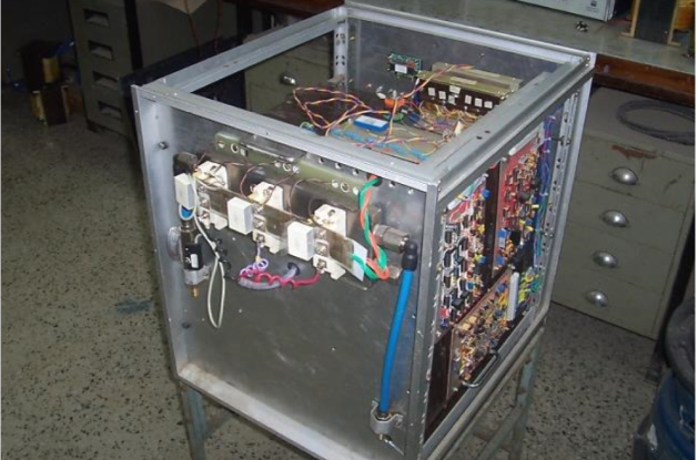
A field mapping power supply is being used for characterising the various types of magnets. During the commissioning of Indus-2 this supply was used for field mapping of Dipole magnets.
Features:
- Current Controlled power supply
- High load current long term stability (+/- 50 PPM)
- SCR controlled pre regulator followed by Transistorised series pass regulator.
- The SCR Bridge is 6-pulse converter in primary of 3-ph transformer is operated as pre regulator. The secondary of transformer is rectified by 12-pulse rectifier and followed by a transistorised series pass.
- The series pass regulator operates in voltage and current control mode.
- Major power components such as SCR, Chokes and power transistor are water-cooled
- Max current: 900A
- Max voltage: 60V
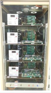
- 3.15 Design and development of Power Supplies for Fast corrector Magnets of Indus-2
To correct the beam orbit of Indus-2 against various disturbances of up to about 50 Hz, a Fast Orbit Feedback (FOFB) system is being developed. In this system, 80 corrector magnets are to be used in Indus-2 ring. Accordingly 80 power supplies are required to energize these magnets. 8 supplies are mounted in a rack. The 4 quadrant converter topology with MOSFET as switching device has been used. The load current bandwidth is 400 Hz. The load for these power supplies are air core magnets.
Features:
- Current Controlled power supply
- High load current long term stability (± 50 PPM)
- Power supply configuration: True bipolar 4 quadrant converter.
- Max current: ±15A
- Max voltage: ±90V
- Load current small signal bandwidth: 400 Hz
- All the power components such as MOSFETs, Chokes and transformer are air cooled
|
|
Power supplies for Fast Corrector Magnets required in Indus-2 for FOFB system |
- 3.16. Design and development of High Stability Power Supply
A high stability digitally controlled current regulated power supply has been designed and developed to cater to the needs of the next generation high brilliance accelerators. Its control algorithm and communication interface has been implemented in DSP. The power circuit consists of a 3 phase diode rectifier, LC filter and an H-bridge switching converter. The output L-C filter is damped using passive components. The H-bridge which consists of MOSFETs as switching devices is switched at 50 kHz using unipolar switching scheme. The load current is sensed by a precision DCCT and digitized by 24-bit sigma-delta type ADC. The load voltage is digitised by 18-bit SAR type ADC. The control structure uses an outer current loop cascaded with the inner voltage loop. The observed load current stability of the power supply current is better than ± 2.5 μA/A over a period of 8 hours, while the current ripple is within ± 2 µA/A.
|
High Stability Power Supply |
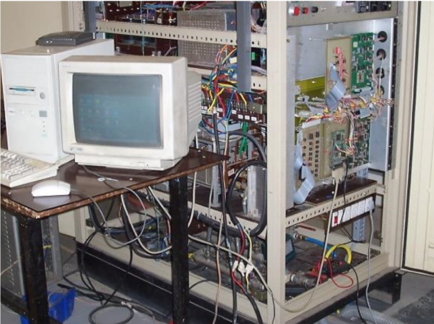
- 3.17. Design and development of SCADA System for Remote Control and Monitoring of Vacuum Furnace
A vacuum brazing facility (vacuum furnace) has been developed at RRCAT for joining aluminium alloys and making bimetallic joints between aluminium and austenitic stainless steel that are compatible with ultra-high vacuum requirements of particle accelerators. The vacuum brazing of aluminium alloys requires precisely control of heat cycles, accurate multi-point thermometry, ultra-clean vacuum, and a system for controlling and monitoring the heating process.
A Supervisory Control and Data Acquisition (SCADA) system has been developed in the Accelerator Power Supplies Division to remotely program, supervise, control, and regulate heat cycles of the vacuum furnace up to 620°C. The SCADA system, follows a modular architecture comprising of a data acquisition system and Open Source Python based graphical user interface (GUI) running on the remote PC. Along with the development of the supervisory and control software, the closed loop PID control has also been implemented for control of the furnace temperature. To arrive at the proper PID coefficients, a systematic study was carried out on establishing the model of the furnace; wherein the highly temperature dependent parameters like thermal resistance and the system time constants around a few discrete points over the operating temperature range were found out.
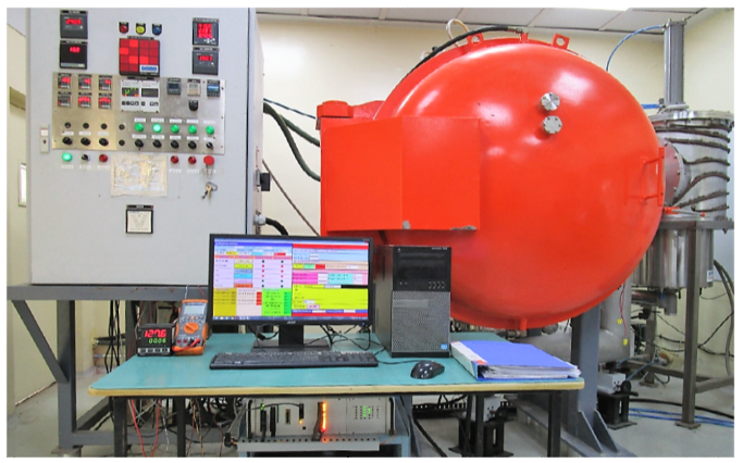
SCADA system for vacuum furnace deployed at DMTD
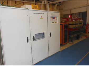
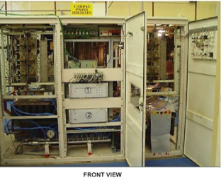
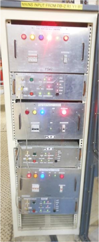
- 3.18. Design and development of Auto Transfer Switch (ATS) for emergency and critical loads of Indus Complex.
A 40 kVA UPS powers emergency and critical loads of Indus Accelerator Complex such as emergency lights, surveillance system, radiation safety systems, public address system, fire detection and alarm system, UHV system, beam line front ends and control data system. The UPS is generally powered through the incoming mains supply connected to the main power terminals and alternate power terminals connected to alternate power source (eg. DG sets). The UPS normally operates on mains power and when mains supply fails, the load is powered through battery banks. When the battery bank discharges to its cut-off limits or in case of any fault in the inverter, the load shifts to bypass mode and is powered through alternate power source. If alternate power source is not available, the UPS shuts down.
An Automatic Transfer Switch (ATS) has been developed for the UPS to automatically switch load from mains to DG power and its operation logic is described below:
- In normal mode, i.e., when main is available, the UPS connected loads are powered through mains power (via rectifier and inverter) and parallelly, the battery bank also charges.
- In case of mains power failure, the load is powered through the battery bank (via inverter) until the DG set starts and its terminal voltage reaches up to the required level (20 seconds). As the terminal voltage reaches the required level, the load is shifted to DG power.
- When the mains power restores, the UPS connected loads are shifted to mains after 15 sec-onds and the battery bank is also charged parallelly.
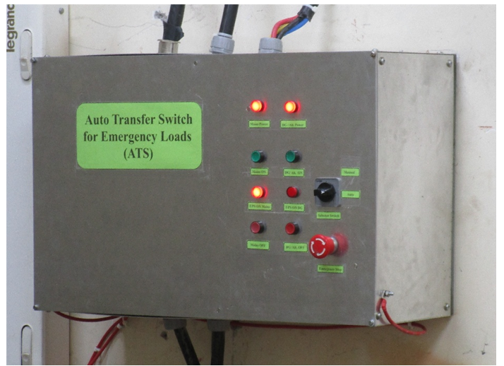
Auto Transfer Switch for emergency and critical loads of Indus Complex
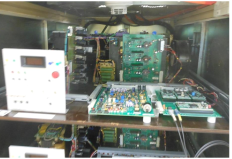
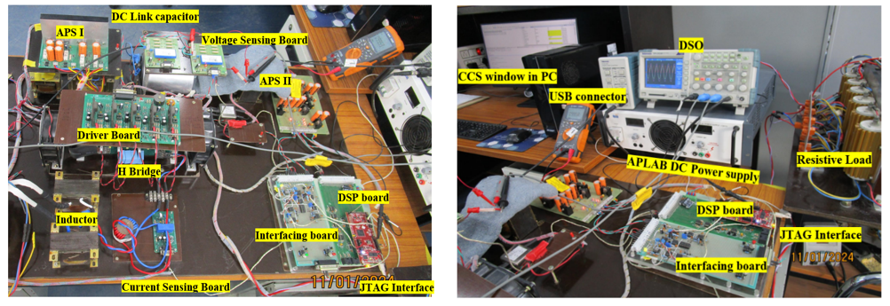
- 3.19. Design and development of digitally controlled PWM Rectifier for harmonic reduction and bidirectional power flow
Most conventional power supplies that employ either uncontrolled or controlled rectifiers as pre-regulators or main regulators suffer from poor line harmonic distortion and low power factor. To address these limitations, a Pulse Width Modulated Rectifier (PWMR) is used as the utility interface. This approach effectively mitigates harmonic distortion and improves the input power factor, albeit at the cost of additional control and power electronic circuitry. The PWMR employs a dual-loop control strategy consisting of an outer voltage loop and an inner current loop implemented using DSP. Control loop simulations are carried out to analyze the dynamic behaviour of the PWMR, and Proportional–Integral (PI) controller parameters are tuned to achieve optimal performance. Digital controller implementation, and experimental validation are performed to minimize line-side harmonic pollution, enhance the input power factor, and enable bidirectional power flow. The photographs of prototype setup are given below.
Specifications:
- Maximum DC load voltage : 100 V
- Maximum DC load current : ±5 A
- Input power factor : > 0.98
- THD in line current : < 6 %
- Power transfer efficiency : > 88 %
|
Power supplies for Fast Corrector Magnets required in Indus-2 for FOFB system |
- 3.20. Design and development of FPGA based digitally controlled power supply for Magnetic characterisation of Indus accelerator magnets
A digitally controlled, dual closed-loop power supply has been developed using Xilinx Spartan-6 FPGA and Verilog HDL. It offers real-time control and monitoring through a capacitive touch HMI and custom GUI. The firmware uses 64-bit double-precision floating-point arithmetic, with loop gain parameters adjustable via the HMI to suit varying load requirements.
Load current and voltage are digitized using 18-bit ADC, which are mounted on swappable piggyback modules to allow flexibility in accuracy and resolution. The power stage consists of an uncontrolled rectifier and an H-bridge using MOSFETs, operating at a switching frequency of 50 kHz. The current version supports ±15 A and ±50 V.
The power supply has been specifically developed for magnetic characterisation of indus accelerator magnets at AMTD. Its modular, floating-point-based architecture is scalable to higher power ratings and serves as a robust platform for future digital power supply development for HBSRS.
A photograph of the system is shown below.
|
Real Time FPGA controlled Power Supply |
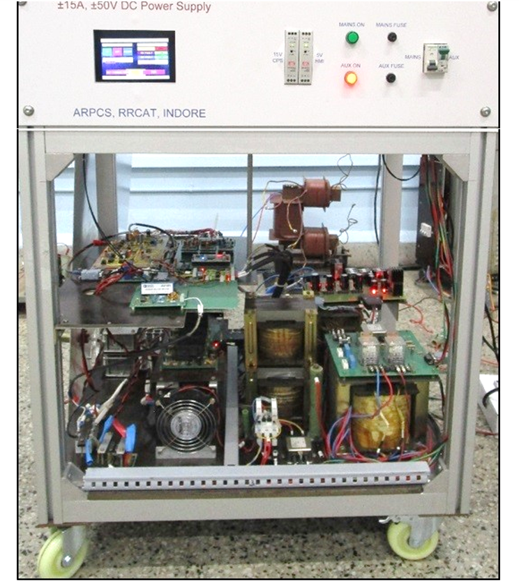
- 3.21. Design and assembly of Wave-Length Shifter DC Power Supply (135A/150V, ±50 ppm)
The Wave-Length Shifter (WLS) required for Indus-2 facilities will enhance photon beam production in harder X-ray range for advanced imaging and material analysis. These wavelength shifters are pivotal for optimizing particle accelerators and synchrotron light sources, enabling diverse scientific and industrial applications. It has been planned to design and develop an output current controlled DC power supply (135A/150V, ±50 ppm) to energize the WLS. The assembly of WLS DC power supply for normal conducting poles of wavelength shifter magnet for Indus-2 is near its completion. A photograph taken during the fabrication has been shown in fig 1.
|
Snapshot of WLS fabrication |
4. Publications
- 4.1. Journals:
- Jena, Saroj Kumar, Husain Riyasat, Gandhi M. L., Agrawal R. K., Yadav S., and Ghodke A. D.,
"Beam based alignment and its relevance in Indus-2,"
Review of Scientific Instruments, 86, 093303 (2015), DOI:http://dx.doi.org/10.1063/1.4930277, September 18, 2015.
- Sheth S.S., Dipanjan Jana, Joshi O.P., Oak S.M.,
"DSP-based Motion Control System."
Journal of the Instrument Society of India, Vol. 38, no. 2, p. 137-144, Jun. 2008.
- Mahadevan S., Gandhi M. L., and Nandedkar R. V.,
"A pulsed electron gun for the Plane Wave Transformer Linac,"
in Nuclear Instruments and Methods in Physics Research Section A: Accelerators Spectrometers Detectors & Associated Equipment; Vol. 496, no. 1, January 2003,p. 26-32.
- Sheth S.S., Choudhary P. Nath A.K.,
"Computer Numerical control system for two axes laser work-station."
IETE Journal of Research, Vol. 49, no. 1, p. 59-66, Feb. 2003.
-
4.2.Conferences / Symposiums:
- Aradhana Kumari, M. L. Gandhi, K. Gopi and U. Yadav,
"Comparative Study of Tracking Error for Booster Synchrotron Power Supply: Effects of Reference Profile Variations and Feedforward Compensation in Fast-Ramped Power Supply,"
International Conference on Power Electronics Converters for Transportation and Energy Applications (PECTEA), Jatni, India, 2025, pp. 1-6; DOI: 10.1109/PECTEA61788.2025.11076298
- Aradhana Kumari, Kandipalli Gopi, Manoj Leelachand Gandhi, Deep Chand
“Developmental Progress of 135 A/150 V DC Power Supply for Wave-Length-Shifter Magnets Based on Performance of Scaled-down Power Converter Scheme”
12th Indian Particle Accelerator Confer-ence-2025 (InPAC-2025), Indore, India, March 2025
- Bhanuprakash B., Gandhi M.L., Sheth S.S., Ansari M.S.
“Digitally Controlled PWM Rectifier for Harmonic Reduction and Bidirectional Power Flow,”
2024 IEEE International Conference on Power Electronics, Drives and Energy Systems (PEDES), Mangalore, India, Dec., 2024, pp 1-6; DOI: doi.org/10.1109/PEDES61459.2024.10961472
- Seema Singhai Sheth, Lalit Biranwar, Manoj Leelachand Gandhi, Sanjeeva Ramteke, Abhay Kumar,
“SCADA System for Remote Control and Monitoring of Vacuum Furnace for Aluminium Brazing,” Indian Particle Accelerator Conference, InPAC-2022; Variable Energy Cyclotron Centre, Kolkata, India, March 2022
- Ujjwal Yadav, H K Khatwani, Mangesh Borage, M L Gandhi, Sunil R Tiwari,
“Experimental Comparison of Half-Bridge DC-DC Converter using Silicon and Silicon Carbide MOSFETs,” IEEE 10th National Power Electronics, Bhubneswar, India, December 2021, DOI: 10.1109/NPEC52100.2021.9672493,https://doi.org/10.1109/NPEC52100.2021.9672493
- H. K Khatwani, S. N. Singh, M. L. Gandhi1, R. Banwari1 and A. C. Thakurta,
“Design and Development of Versatile and Modular Digital Control System for Power Converters of Accelerator,”
in 9th Indian Particle Accelerator Conference, New Delhi, November 18-21, 2019.
- Anil kumar, H. K. Khatwani1, M. L. Gandhi1, V. D. Sharma1, R. Banwari1, and A. C. Thakurta,
“Design, Installation and Commissioning of Smoke Exhaust System For Experimental Hall at Indus-2 Accelerator Complex,”
in 9th Indian Particle Accelerator Conference, New Delhi, November 18-21, 2019.
- Aradhana Kumari, M. L. Gandhi, and A. C. Thakurta,
“Development of Methodology for Qualification of Per-Formance of Active Shunts during their Mass Production,”
in 9th Indian Particle Accelerator Conference, New Delhi, November 18-21, 2019.
- A. Kumari, M. L. Gandhi, L. Srinivas, A. C. Thakurta,
"Development of Active Shunts for Quadrupole Magnets and their Production Status; and their Role in Indus-2,"
Proceedings of the 8th Indian Particle Accelerator Conference – 2018.
- H. K. Khatwani, M. L. Gandhi, S. N. Singh, A. C. Thakurta,
Design and Implementation of a Digitally Controlled High Stability Power Supply for Accelerator Magnets,"
Proceedings of the 8th Indian Particle Accelerator Conference – 2018
.
- Gandhi M. L., Srinivas L., and Thakurta A. C.,
"Bipolar active shunt with bidirectional utility interface for the quadrupole magnets of Indus-2,"
in 9th IEEE International Conference on Industrial and Information Systems (ICIIS), Gwalior, December 15-17, 2014.
- Singh S. N., Singh T. N., Khatwani H. K., Gandhi M. L., and Thakurta A. C.,
"Fast Corrector Magnet Power Supplies for Indus-2,"
in Indian Particle Accelerator Conference, VECC, Kolkata, November 19-22, 2013.
- Srinivas L., Pandey R. M., Yadav R. P., Gupta S., Gandhi M. L., and Thakurta A. C.,
"Automation of Secondary Loop Operation in Indus-2 LCW Plant,"
in Indian Particle Accelerator Conference, VECC, Kolkata, November 19-22, 2013.
- Kak Ajay, Kher A., Vishwakarma S. C., Kumar Abhay, Gandhi M. L., Radheshyam Pramod, and Lala Abhinandan,
"Fabrication of a Ultra High Vacuum compatible Faraday Cup for qualification of Electron Gun for 10 kW industrial LINAC,"
in Proc. of International Symposium on Vacuum Science & Technology and Its Application for Accelerators, Kolkata, February 15-17, 2012.
- Gandhi M. L., and Thakurta A. C.,
"High stability bipolar current power supply for a variable pole gap dipole magnet,"
in Indian Particle Accelerator Conference - 2009 (InPAC-09), RRCAT, Indore, February 10-13, 2009.
- Gandhi M. L., and Thakurta A. C.,
"Power Quality Performance of an Active Harmonic Filter with a Power Converter Feeding Magnet Load"
in Third IEEE International Conference on Industrial and Information, IIT Kharagpur, December 8-10, 2008.
- Karandikar U. S., Singh Y., Gandhi M. L., Thakurta A. C., and Kotaiah S.,
"Current control mode fly-back as CCPS,"
in Indian Particle Accelerator Conference - 2006 (InPAC-06), Mumbai,
- A Kumari, M. L. Gandhi, L Srinivas, A C Thakurta,
"Development of Active Shunts for Quadrupole Magnets and their Production Status; and their Role in Indus-2,"
Proceedings of the 8th Indian Particle Accelerator Conference – 2018. November 1-4, 2006.
- Gandhi M. L., Singh S. N., Thakurta A. C., and Kotaiah S.,
"Performance of A DSP based phase-shifted PWM controlled, zero-voltage-switching direct-current regulated magnet power supply,"
in IEEE Power India Conference, New Delhi, India, April 10-12, 2006, p. 191-197.
- Singh S. N., Gandhi M. L., and Kotaiah S,
"Digital Control of Quadrupole Magnet Power Supply using TMS320F2812 DSP,"
in SEBTA 2005, Mumbai, September, 28-30, 2005.
- Gandhi M. L., Thakurta A. C., and Karandikar U. S.,
"Mitigation of Stability Problems of Pulsers For Injection Kicker Magnets of Indus-II,"
in Indian Particle Accelerator Conference - 2005 (InPAC-05), VECC, Kolkata, March 1-5, 2005, p. 447-448.
- Gandhi M. L., Thakurta A. C., and Kotaiah S.,
"Power Supplies for Transport Line - 3 Quadrupole Magnets,"
in Indian Particle Accelerator Conference - 2003 (InPAC-03), CAT, Indore, February 3-6, 2003, p. 404-406.
- Mahadevan S., Gandhi M. L., and Nandedkar R.V.,
"Design and fabrication of a Pulsed Diode Electron Gun,"
in Indian Particle Accelerator Conference - 2003 (InPAC-03), CAT, Indore, February 3-6, 2003, p. 299-300.
- Tiwari S. R., Thakurta A. C., Thipsay A. P., Pagare A., Gandhi M. L., Singh T., Singh S., and Kotaiah S.,
"Power Supplies for Indus-1,"
in Asian Particle Accelerator Conference - 1998 (APAC-98), Tsukuba, Japan, March 23-27, 1998.
- Sheth S.S., Sheth Y.M., Fakhri A.A., Prajapati S.K., Baxy D.
"Nonlinear Reference Profile Generator for Quadrupole Supplies of Booster Synchrotron"
Indian Particle Accelerator Conference , Indore, Jan., 9-12, 2018.
- Sheth S.S., Sheth Y.M.*, Kumar S., Satheesan T.V., Francis A., Fatnani P., Navathe C.P. ,
"Power Supply Control Module for Magnet Power Supplies Control System of Indus-1"
Indian Particle Accelerator Conference , VECC, Kolkata, Nov., 19-22, 2013
- Sheth S.S., Joshi O.P., Oak S.M.,
"DSP based Embedded PMDC servo motor drive for Laser Material Processing"
National laser symposium , Baroda, Dec., 17 - 20, 2007
- Sheth S.S., Joshi O.P.,
"Nath A.K.Control system for five axes Laser Robot"
National Symposium on Instrumentation- 30 , Cochin, Nov 30 - Dec 2 , 2005
- Sheth S.S., Joshi O.P., Gupta C., Nath A.K. ,
"Permanent magnet DC servo motor based speed and position controller for laser material processing"
National Laser Symposium - 2003, IIT, Kharagpur, Dec., 22-24, 2003
- Sheth S.S., Bhargava P., Joshi O.P., Nath A.K.,
"Computer Numerical Control System For Three Axes Work-Station"
National laser symposium , Indore, Dec., 19-21, 2001
- Sheth S.S., Paul C.P., Joshi O.P., Nath A.K.,
"Embedded motion control system with pulse width modulated stepper motor drives for laser based rapid prototyping"
National laser symposium , Indore, Dec., 19-21, 2001
4.3.RRCAT Newsletter:
- Seema Singhai Sheth
“SCADA System for Remote Control and Monitoring of Vacuum Fur-nace.”
RRCAT Newsletter, A4, Volume 36, Issue 1, 2023
- Seema Singhai Sheth, Yogendra Sheth and P. Fatnani
"New control system for magnet power supplies of Booster Synchrotron"
RRCAT Newsletter, A2, Volume 29, Issue 2, 2016.
- M. L. Gandhi, and Lingam Srinivas,
"Active shunt for Indus-2 quadrupole magnet for beam based alignment study,"
in RRCAT Newsletter, A6, Volume 28, Issue 2, 2015.
- Seema Singhai Sheth and P. Fatnani
"New Control System for Magnet Power Supplies of Transport Line-l of Indus-1"
RRCAT Newsletter, A12, Volume 26, Issue 2, 2013.
|
|