| Proton Linac Development Division |
 |
|
Engineering Design and Development Drift Tube Linac (DTL)
In the present scheme of 1 GeV H- ion linac, drift tube linac (DTL) would be used for accelerating H- ions from 3 MeV to 13 MeV. DTL requires RF power for acceleration of beam and this results in heat load on the walls of drift tubes and DTL tank. As a part of engineering design, cooling design has been carried out for drift tube and DTL tank. And to check adequacy of cooling design, analysis has been carried out for drift tube and DTL tank. Fig. 1 shows the solid model for DTL and Fig. 2 shows the solid model for drift tube. To predict frequency-shift due to RF heat, coupled multi-physics analysis has been carried out. Analysis has been carried out for two cells of drift tube along with DTL tank. Fig. 3 shows the model for two cells in DTL for which HFSS analysis was carried out. Fig. 4 shows normalized electric field in DTL. Fig. 5 shows the temperature distribution and deformation in DTL at 10% duty factor.
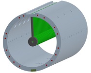
Fig.1: Solid model for DTL
|

Fig.2: Solid model for drift tube (DT)
|
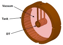
Fig.3: Model for HFSS analysis
|
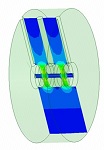
Fig.4: Normalized electric field in DTL
|
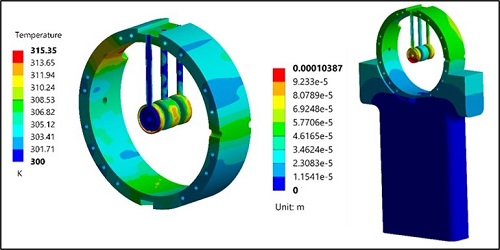
Fig.5: Temperature and deformation in DTL at 10% duty factor
|
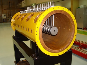
Fig.6: Assembly of prototype DTL tank with drift tubes
|
|
|
|