Accelerator Physics Section
Section is involved in the physics design of Synchrotron Radiation (SR) sources namely, Indus-1(450 MeV electron storage ring) & Indus-2(2.5 GeV electron storage ring). It is also involved in the physics design of its injector, namely booster synchrotron and beam transfer lines connecting various accelerators. It provides beam dynamics support towards the improvement, up gradation and participation in round the clock operation of SR sources, where the main objective is to provide the photon beam to the beam line users from all corners of India for carrying out scientific research using SR in various domains. The section is engaged in the physics design of High Brilliance Synchrotron Radiation Source (HBSRS). Also it is involved in physics design of electron guns for 10 MeV linac of ARPF and an electron gun for testing of photon absorbers of HBSRS project.
Group Activities
Publications
Group Members
Design, commissioning and operation of Indus-1 and Indus-2
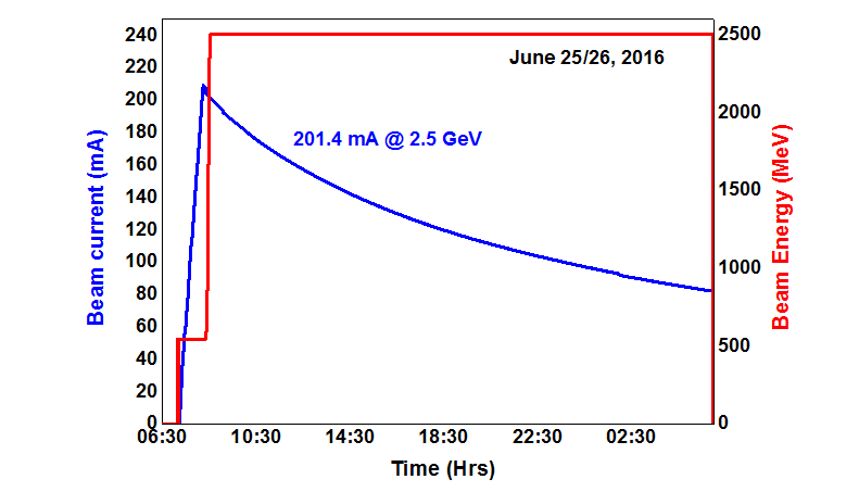
Two SR sources namely Indus-1 and Indus-2 are housed in RRCAT. A beam dynamics based lattice design of these SR sources along with their common injector namely booster synchrotron was evolved. The design study of the lattice is being carried out using various computational code named as MAD, ORBIT, AT, ELEGANT and RACETRACK. Apart from the lattice design, design of transfer line and study about beam injection and extraction, closed orbit distortion, and different beam instabilities are also being carried out. These studies are made using the centralized scientific computing servers (BETA, CHI, DELTA, and AMOGH) and scientific computing clusters (KSHITIJ) at RRCAT. These simulations help in finalizing the design and tolerances of various components of the accelerator. These radiation sources have been commissioned successfully and are being operated in round the clock mode near to the design beam parameter. Most of the members of our section had undergone the rigorous training and qualification tests for the operation of these sources and contributing as beam physicists for reliable and smooth operation. Indus-2 is successfully operated with a beam current of ~200 mA at 2.5 GeV as shown in figure below
|
Operation of Indus-2 at 200 mA @ 2.5 GeV |
Beam injection dynamics
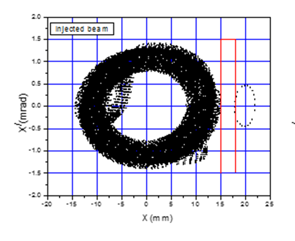
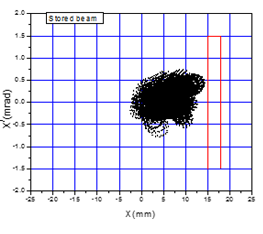
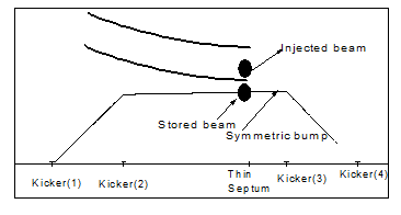
In booster, Indus-1 and Indus-2, three, single and four injection kicker schemes are adopted respectively to carry out multi-turn beam injection. The performance of booster in terms of accelerated beam current is better in uncompensated bump injection scheme as compared to compensated bump injection scheme. Indus-2 was commissioned and operated with moderate optics to overcome several difficulties faced in the beam injection with a low beam emittance optics. These difficulties are mainly governed by the higher strength of chromaticity correcting sextupole magnets. In the low emittance optics, due to higher strength of chromaticity correcting sextupole magnets, dynamic aperture is smaller as well as during beam injection injected and stored beam oscillations are higher as compared to the moderate optics. Even for the moderate optics, the maximum amplitude of injected and stored beam oscillations are reaching near to the septum magnet, which is shown in adjoining figure. The amplitude of these oscillations are reduced with the help of off momentum beam injection.
|
|
A) Injected beam oscillation |
B) Stored beam oscillation |
Injected and stored beam oscillations in the presence of mismatch between injection kickers
|
Betatron tune feedback
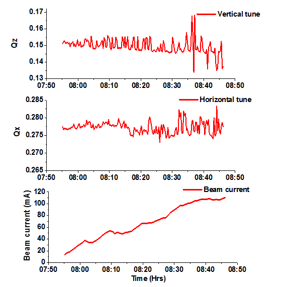
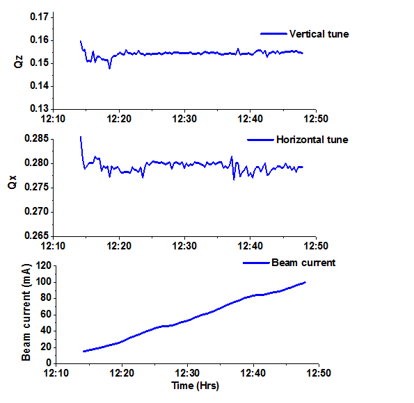
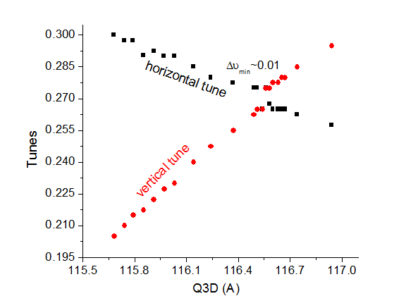
Betatron tune is a key beam parameter, and a fixed desired tune is essential in a synchrotron radiation facility. In Indus-2, difficulty was faced in smooth accumulation of beam current and it was observed, shifting of betatron tune in a random manner is the main cause behind it. Thus, to control the shift in tune, a betatron tune feedback system was implemented for which two appropriate quadrupoles families were identified by analyzing the machine response matrix. Tune feedback system is able to control the betatron tune in both the transverse plane within the range of 0.001. This helps in smooth accumulation of beam current in Indus-2 as shown in figure.
|
|
| a) Tune feedback OFF |
b) Tune feedback ON |
Beam current accumulation with tune feedback ON and OFF |
Ion trapping investigation
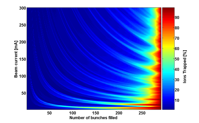
In Indus-2, several times beam current saturation was observed when the stored beam current reached around 100 mA. After several experimentation and simulation, it was concluded the presence of ion trapping is also the main cause behind it. To overcome the effect of ion trapping, simulation study was carried out and a suitable bunch filling scheme was evolved by which the disturbing effects caused by the ions were mitigated. The stability of ion species throughout the Indus-2 ring was estimated using various configurations of bunch trains and the simulation result for the CO+ ion is shown in the adjoining figure. This figure suggests that to mitigate the ion trapping problem, a bunch filling pattern consisting of a long train of 150 consecutive bunches out of 291 bunches is an optimized solution. With this optimal partial bunch filling pattern, higher beam current accumulation was achieved in Indus-2.
|
Percentage of region of ring circumference where the CO ions are trapped for various length of bunch train in the Indus-2 |
With the improvement of vacuum pressure in the ring, attempt was made to fill a maximum number of bunches to reduce per bunch current which helps in suppressing resistive wall instability. For this bunch filling pattern was optimized with appropriate bunch gaps with an aim to minimize the effect of ion trapping problem. Subsequently the beam was accumulated with two bunch trains and each train having 128 filled bunches and 17 bunch gaps. This bunch filling pattern could suppress coupled bunch instability which appears in single train bunch filling with 150 bunches. It also helps in accumulating high beam current without the use of transverse multi bunch feedback system and concurrently, this becomes a regular filling pattern in Indus-2 operation.
Closed orbit correction and Beam-based alignment (BBA)
Closed orbit correction
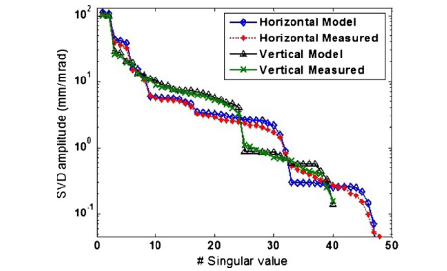
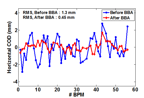
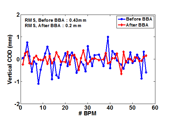
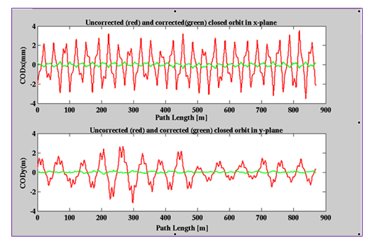
In real operation of any circular accelerator, there are magnet-to-magnet field errors, stability errors of power supplies driving the magnets, misalignment of the magnetic elements etc. These errors distorts the ideal path known as closed orbit distortion (COD). The COD degrades performance of the storage ring in terms of poor beam injection, reduced beam lifetime and most importantly, improper photon beam delivery to the users. Therefore, it is necessary to correct the COD all over the ring. For the measurement of COD, there 56-beam position monitors (BPMs) distributed all over the ring and for its correction, 48 horizontal and 40 vertical orbit corrector magnets are installed. It is a COD minimisation problem based on orbit response matrix (ORM) between changes in orbit at BPMs with known change in corrector current. The SVD of the model and measured ORM in both the planes is shown in top figure. The RMS COD was reduced to 0.3 mm and 0.2 mm from 4.5 mm and 1.7 mm after integrating the BPM offsets determined by beam based alignment (BBA) technique and taking corrective action, which is shown in bottom figure.
|
Comparison of singlura value decompostion of the measured and model ORM. |
|
|
Corrected horizontal and vertical COD before and after incorporating the BPM offsets |
Beam Based Alignment (BBA)
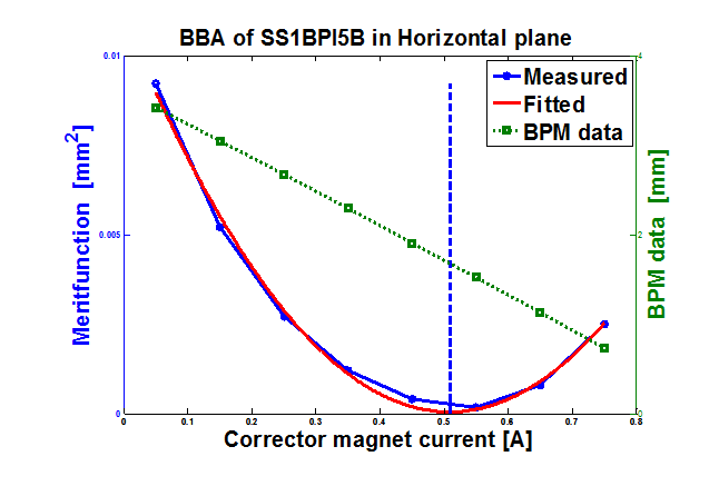
The main objective of this BBA is to pass the electron beam through centre of magnetic elements of the Indus-2 ring. For this, the offsets of all the 56 beam position monitors (BPM) distributed over the ring were determined using beam-based alignment (BBA) technique. The process of finding the offset was very cumbersome and hence made fully automated. One such offset measurement is shown in figure below. After the BBA measurement, the offsets were incorporated in BPM system for further COD correction. This exercise, resulted into reduction of COD of Indus-2 substantially in both the horizontal and vertical plane. With this correction, more aperture was available to the beam and that enhances beam lifetime in Indus-2 significantly.
|
Offset determination for the BPM in Indus-2 using beam based alignment (BBA) |
Characterization of beam optics
LOCO analysis
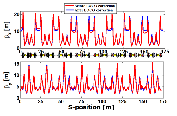
The estimation and correction of the beam optics errors in the operational storage ring is always vital to achieve the design performance. To achieve this task, a method based on linear optics from closed orbit (LOCO) is used in Indus-2 storage ring. In this technique, based on the response matrix fit, errors in the quadrupole strengths, BPM gains, orbit corrector calibration factors etc. are obtained. The methods based on Gauss-Newton and Levenberg Marquadt are used for fitting. For correction of the optics, suitable changes in the quadrupole strengths are applied through the changes in currents of the 26 quadrupole power supplies to achieve the desired optics. The beta function and betatron tunes before and after optics correction are shown in figure. Betabeat, which is the relative deviation of the beta function, has been reduced to better than 1% from uncorrected values of ~9% in horizontal and ~ 6% in vertical plane. After the optics correction, the performance of the storage ring is improved in terms of beam accumulation, reduced beam loss during energy ramping, and beam lifetime etc.
|
|
Betatron function in both horizontal and vertical planes before and after applying the LOCO correction. |
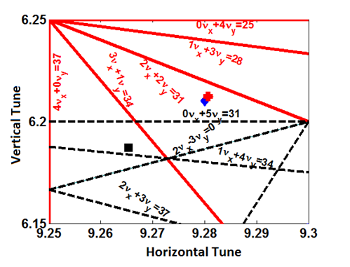
Tune diagram up to the 5th order resonances. At 2.5 GeV, the theoretical betatron tune is shown by a plus symbol, the square and the diamond symbols show the measured betatron tunes before and after optics correction using 26 quadrupole power supplies. The corrected betatron tune matches very closely to the theoretical model value. |
Betatron coupling measurement in Indus-2
The achievement of bright beam with a better lifetime are one of the challenges in designing synchrotron radiation sources. In a real machine, there may exist rotation error about the longitudinal axis in normal quadrupoles and because of that the electron displaced in horizontal plane experience an extra force in vertical plane and vice-versa. Due to this coupling phenomena between horizontal and vertical motion of electrons, it give rise to vertical emittance in storage ring. The rotated quadrupole in dispersive region will give rise to vertical dispersion and due to this, there is also an increase in vertical beam emittance. For getting bright beam, vertical emittance should be minimum. Betatron coupling and residual vertical dispersion has been measured in Indus-2 storage ring. The measurements of betatron coupling was carried out using tune split method and using Cross Talk Closed Orbit (CTCO) method. The results are shown in figure. The measured betatron coupling was found to be less than 1%.
|
|
Betatron coupling measurement using tune split method |
Measured vertical dispersion at all BPM locations in Indus-2 |
Design, commissioning and impact on beam dynamics of undulators
Specification of two planer undulators U1& U2 and one helical undulator U3 were evolved using beam dynamics simulation in Indus-2. With the designed specifications, these magnets are installed and commissioned. All three undulators have been successfully operated with the beam in Indus-2. Their effects on electron beam are measured and found to be in good agreement with the model predictions. Both the planer undulators U1 & U2 are operated with stored beam current of 150 mA and Apple-II undulator (U3) was operated with 100 mA at 2.5 GeV.
Impact of undulator on Beam dynamics
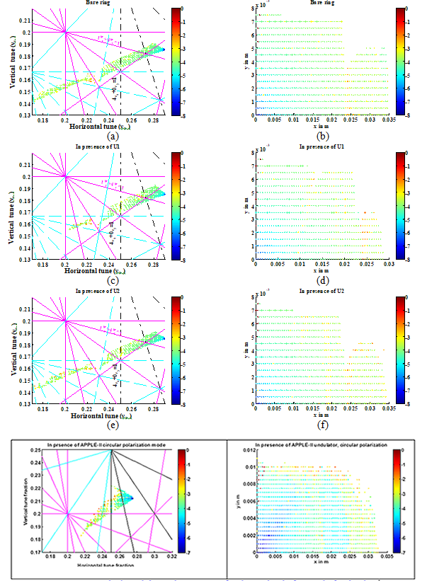
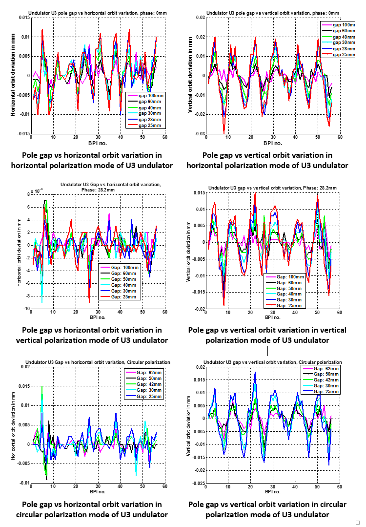
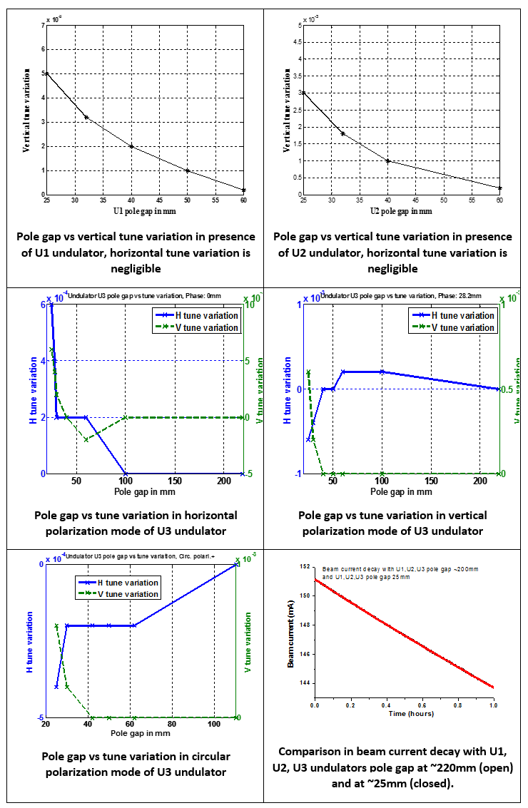
The magnetic field of undulator introduces perturbations in the path of the circulating electron beam and hence affect the linear and nonlinear beam dynamics of the electron beam in a storage ring. Study of the perturbations is essential for two purposes: first, to avoid degradation in the performance of the storage ring and second, to avoid any variation in the synchrotron radiation photon beam characteristics, which are primarily defined by the electron beam parameters at the radiation source point. In this context, study of tune, beta, emittance, and energy spread variation was carried out. Measurement results of tune and beta variations are in good agreement with the theoretical calculations. Emittance and energy spread variations are found to be very small. The impact of nonlinear perturbations are analysed with the help of Frequency Map Analysis (FMA), and is shown in figure. This reveals that the nonlinear perturbations induced by undulators fields are not affecting the performance of the storage ring. The measured orbit and tune variations and beam current decay with different pole gaps of undulators U1, U2 and U3 are also shown below:
|
Frequency map analysis and dynamic aperture of Indus-2 ring before and after having undulators U1, U2 and U3 |
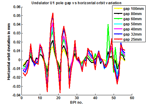
Pole gap vs horizontal orbit variation in presence of U1 undulator |
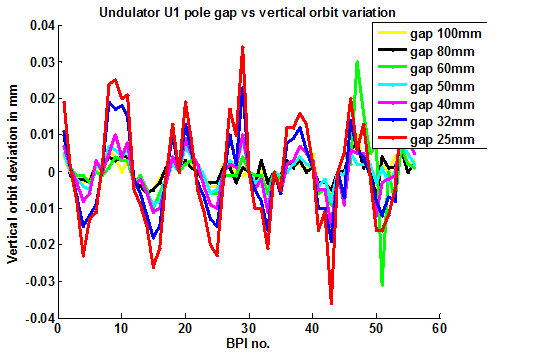
Pole gap vs vertical orbit variation in presence of U1 undulator |
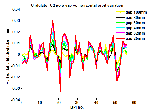
Pole gap vs horizontal orbit variation in presence of U2 undulator |
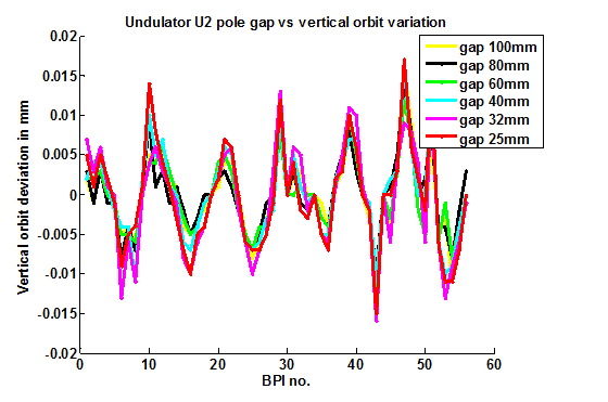
Pole gap vs vertical orbit variation in presence of U2 undulator |
Effect on vertical beam size by change in row phase of APPLE-II undulator
In electron storage rings, Advanced Planar Polarized Light Emitter (APPLE) undulators are installed for generating high brightness photon beam with variable polarization. The variable states of polarization of photon beam are achieved by changing the row phase of the undulator. The change in row phase and pole gap generate the skew quadrupole gradient error which can cause significant change in vertical beam size resulting into the degradation of photon beam brightness. The measured data of skew quadrupole field generated with the change in row phase in APPLE-II undulator installed in Indus-2 was obtained from magnet group. The effect of this skew quadrupole field on vertical beam size was estimated and found to agree with measured results.
The polarization of the APPLE undulator radiation is controlled by changing the row phase and photon energy is controlled by changing the pole gap. It is observed that while changing pole gap and row phase, there is significant change in vertical size of electron beam and it leads to variation in brightness of emitted photon beam which affect the experiments of synchrotron radiation users. The variation in vertical size of electron beam is due to generation of skew quadrupole field gradient error with change in pole gap and row phases which couples the electron beam motion in horizontal and vertical plane.
APPLE-II undulator is installed in one of the long straight sections (LS-5) in Indus-2. The total length of complete magnet assemblies of APPLE-II undulator is ~2 m, it has 32 periods, one period length λu ~56.4 mm. The measured magnetic field at minimum undulator pole gap 24 mm (maximum photon energy) with change in row phase is shown in Figure. The measured data of integrated skew quadrupole gradient error gs.l(gs : skew quadrupole gradient, : effective length), with change in row phase at pole gap 24 mm is shown in Figure. The skew quadrupole gradient errors are very sensitive to electron storage rings those operated near to the linear difference coupling resonance (fractional betatron tune in horizontal and vertical plane nearly same). For operating lattice in Indus-2, vertical beam sizes at beam energy 2.5 GeV was estimated without and with measured skew gradient errors using ELEGANT code. The estimated change in vertical beam sizes corresponding to the measured integrated skew quadrupole field gradient errors with the change in row phase at undulator pole gap 24 mm is shown in Figure:
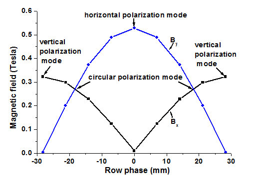
Variation of on-axis magnetic field Bx and By with change in row phase at
24 mm pole gap in APPLE-II undulator
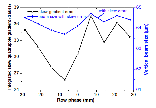
Integrated skew quadrupole gradient errors and vertical beam sizes with change in row phase at 24 mm pole gap in APPLE-II undulator
A beam current ~20 mA was stored at beam energy 2.5 GeV. Initially when APPLE-II undulator (U3) jaw was open (gap ~220 mm), vertical beam size was measured using X-ray diagnostic beam line (BL-24) installed in Indus-2 on DP-10 at 100 port. The undulator jaw was closed (gap ~25 mm). In this condition row phase was changed to study change in vertical beam size. The measured results are shown in Figure.
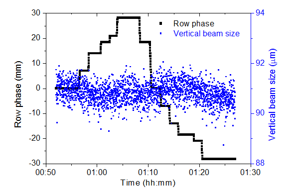
Vertical beam size with change in row phase of APPLE-II
The measured results show that the change in vertical beam size with change in row phase is in band of 1μm. As per the estimation, the change in vertical beam size is ~1 µm which agree with the measured data. The theoretical vertical beam size is ~64μm whereas the measured vertical beam size is ~90μm.
Enhancement of Beam lifetime
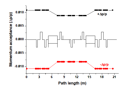
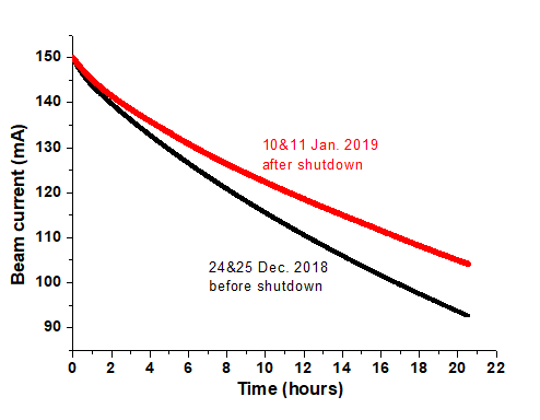
The lifetime of the stored electron beam in a synchrotron radiation source is mainly dominated by beam-gas interactions (vacuum lifetime) and electron-electron interactions within a beam bunch (Touschek lifetime). It depends on the dynamic aperture available for on-momentum and off-momentum electrons for stable motion in storage ring. Horizontal and vertical aperture available for beam motion has been measured using horizontal and vertical scrapers installed in one of the long straight sections in Indus-2 stoarge ring. The vacuum pressure in the ring was not uniform and at ~100 mA stored current at 2.5 GeV was ~ 2×10⁻⁹ mbar at several places in the ring, but it was found quite high and it was ~1×10⁻⁸ mbar, at four injection kicker location. After the replacement of the cracked ceramic vacuum chamber of all four kicker magnets with new ones, the measured vacuum pressure everywhere in the ring was reduced to ~ 1 x 10⁻⁹ mbar at the stored beam current of 100mA. As a result this modifications, beam lifetime of more than 40 hours has been observed at 100 mA stored current at 2.5 GeV beam energy. Thereafter, in December 2018 shutdown, small and minor vacuum leak in segment 4 and 5 was detected. Corrective measures were taken promptly and vacuum pressure in the entire ring was further reduced to 2.5 x 10⁻¹⁰ mbar. After this, beam lifetime of more than 70 hours at 100 mA was achieved which shows a significant improvement. A comparison in beam current decay before and after shut down is shown in figure below. The beam lifetime also depends on the momentum acceptance of the ring. The simulated result of momentum acceptance of the ring at total RF voltage of 1825 kV is shown in adjacent figure, which shows sufficient momentum aperture is available to beam. With this machine condition, Touschek lifetime and vacuum lifetime was calculated using 6D particle tracking code ELAGENT and the total measured beam lifetime is seen to be concurrent with the theoretical estimated value.
|
|
Momentum acceptance in Indus-2 |
Beam current decay pattern before and after shutdown |
Low emittance optimization during operation
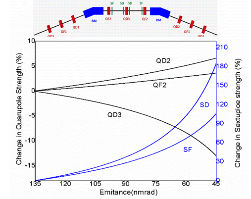
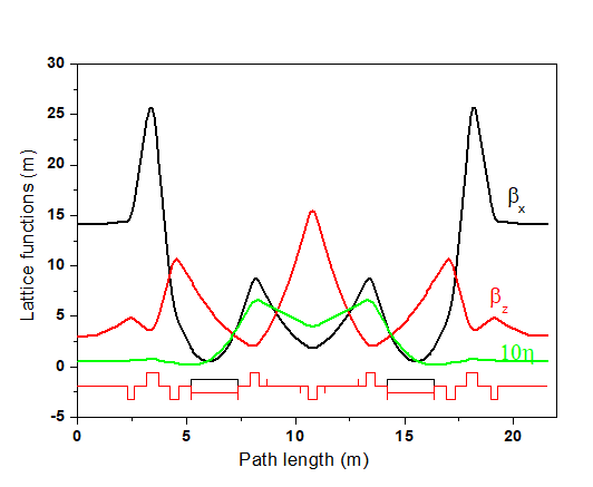
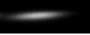
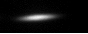
In order to enhance the spectral brightness of Indus-2, an extensive study has been carried out to reduce its transverse emittance. In low emittance mode, difficulties are faced during beam injection in Indus-2. For this, this storage ring was operated at a higher emittance and afterwards its emittance was reduced at 2.5 GeV by using an appropriate switch over procedure with the help of optimal tuning of quadrupole and sextupole magnet power supply currents in a synchronized manner. For switching over to the low emittance mode, strengths of quadrupole and sextupole magnets are adjusted as shown in the figure. After this optics optimization, final tuning of machine was carried out using various feedback mechanism such as transverse bunch by bunch feedback, orbit feedback and tune feedback. These processes reduces the horizontal emittance to ~45 nm-rad from ~135 nm-rad and vertical emittance to ~0.2 nm-rad from ~0.3 nm-rad. Lattice functions for the reduced emittance lattice is shown below. These values are confirmed by measuring the beam sizes on X-ray diagnostic beam-line. In this process, bunch length of electron beam as measured on visible diagnostic beam-line is also found to be reduced by ~40%. Indus-2 operation with reduced emittance will provide the enhanced spectral brightness of photon beam up to factor of ~4. It is also demonstrated that with this procedure, the horizontal emittance can be further reduced up-to 22 nm-rad., the beam spot for moderate and low emittance optics are recorded from sighting beamline and shown in figure below.
|
|
Variation of strengths of quadrupole and sextupole magnets during switch over from nominal operating emittance to reduced emittance |
Lattice functions of low emittance optics having beam emittance of 45 nm-rad |
|
|
Beam spot in moderate optics |
Beam spot in low emittance optics |
Operation with low momentum compaction optics
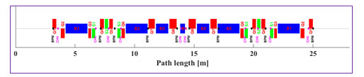
To obtain the short electron bunches, synchrotron radiation storage rings are operated with low momentum compaction optics. The short electron bunch provide two additional tools for SR users. First is the incoherent short synchrotron radiation pulses up to the X-ray regime to perform the time resolved experiments and second is the coherent synchrotron radiation in THz regime. Trial operation is performed to achieve the short electron bunches in Indus-2 storage ring. For this, a modified beam optics as shown in figure below is studied and applied in the storage ring.
Optical function of low alpha lattice
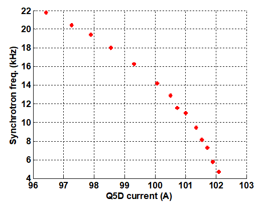
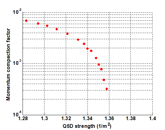
The new beam optics demanded the reversal of the polarities of two quadrupole magnet families and also two sextupoles magnet families as well as retuning of all five quadrupole and two sextupole families. Beam accumulation is carried out at injection energy (550 MeV) using the existing set of four injection kicker magnets, installed in long straight section of the ring. For increasing the beam energy, Indus-2 magnet power supplies current are increased synchronously. There was heavy beam loss (~90 %) during initial stage of beam energy ramping. It was mainly due to excitation of third order resonance. After 2-3 iterations of tune corrections using Q2 and Q3 families of quadrupoles, beam loss was minimized. With 18mA at final beam energy of 2.5 GeV in multi-bunch mode (291 bunches), transition to low momentum compaction optics has been performed by changing the strength of Q5 family quadrupoles. During transition, the quadrupoles of Q2 and Q3 families placed in long straight sections are chosen to correct the betatron tunes as these quadrupoles are less sensitive to change the momentum compaction factor. The measurement of synchrotron frequency during the operation confirms that the momentum compaction factor is reduced by a factor of 25 with 17mA of beam current stored in Indus-2. As a result, the natural bunch length of the electron beam is expected to be reduced by a factor of 4.8 (from 50ps to ~10.4ps). The measured synchrotron frequency and the estimated momentum compaction factor are shown in figure below.
|
|
| Measured synchrotron frequency vs Q5 current during the transition to low momentum compaction optics |
Momentum compaction factor (derived from synchrotron freq.) vs Q5 strength during transition to low momentum compaction optics |
Beam instability and high current operation
For a well-designed electron storage ring, there are two main causes for electron losses; first is due to scattering of particles in the beam with the residual gas molecules and second is due to beam instabilities. While the electron losses due to scattering is a single-particle phenomena leading to a gradual loss of electrons whereas electron losses due to beam instabilities is a multi-particle effect and it can lead to a partial or complete loss of the electron beam. The multi-particle effect arises due to electromagnetic interaction of the high intensity electron beam with its wake fields which are induced due to resistive wall of vacuum chamber, broad band impedance and narrow band impedance of the various storage ring components. The broad band impedance of the ring arises due to non-uniform cross section of the components in the ring like bellows, kickers and beam position indicators whereas narrow band impedance of the ring arises mainly due to RF cavities. The wake fields due to broad band impedance are short range and it causes single bunch instability whereas the wake fields due to narrow band impedance are long ranges and it causes coupled multi-bunch beam instability. In Indus-2 transverse multi-bunch feedback has been installed and is operational whereas longitudinal multi-bunch feedback is to be installed. The longitudinal coupled bunch instabilities arises due to RF cavities higher order modes are suppressed by optimizing the water temperature in the individual RF cavities. With these conditions a beam current ~200 mA at beam energy 2.5 GeV has been stored in Indus-2 storage ring.
High current operation in Indus-2
Synchrotron Radiation flux from a synchrotron radiation source increases at higher beam current, however increasing stored beam current poses challenges due to beam instabilities and heat load on the components. Indus-2 operates in ramp mode, i.e. the injection energy of electron beam (550 MeV) is lower than the final energy (2.5 GeV) in user mode. Therefore, high current operation includes a proper optics and instability control over the energy ramp also. Proper tuning of the different quadrupole magnets, i.e. keeping the betatron tunes away from dangerous resonances, mitigating higher order mode problems to suppress the instabilities by optimized settings of RF cavities temperature and bunch by bunch feedback system in the entire ramping made it possible to increase the beam current to 200 mA at 2.5 GeV, in-spite of varying over voltage factor during energy ramping. Routinely, Indus-2 is now operating at higher beam current for users.
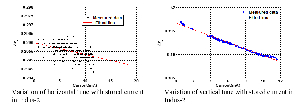
Study of Transverse Mode Coupling Instability in Indus-2
Transverse Mode Coupling Instability (TMCI) is one of the most severely current limiting single bunch instability in large circumference electron storage rings. The mechanism that leads to this instability can be explained in terms of coupling of head-tail modes of an electron bunch. The head-tail instability depends strongly on chromaticity (change in betatron tune with electron energy) however TMCI is weakly dependent on chromaticity and persists even when the chromaticity is zero. With increasing current, the betatron frequency (m = 0 mode) is shifted towards neighboring modes (m = -1 mode). At some particular current, the two mode frequencies coincide each other and excites the instability. To study this instability in Indus-2 at 2.5 GeV beam energy, a simulation is performed by using elegant code. For simulation, transverse impedance (imaginary) of Indus-2 vacuum chamber is taken 45 kΩ/m and 305 kΩ/m in horizontal and vertical plane respectively. This impedance is derived from the measured tune variation with current in Indus-2.
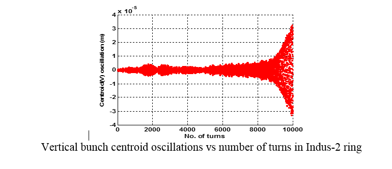
 Simulation results show that single bunch threshold current for TMCI in Indus-2 at 2.5 GeV is ~180mA. At this current level, bunch centroid oscillation is exponentially growing with growth rate of 1.8 ms due to merging of modes m = 0 and m = -1 in vertical plane.
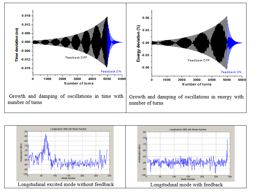
Study of longitudinal coupled bunch instabilities in Indus-2
To get design photon beam quality it is essential to control the longitudinal beam parameters using longitudinal bunch by bunch feedback system. A simulation study on the deviation in beam arrival time and energy in presence of longitudinal coupled bunch beam instabilities at beam injection energy 550MeV in Indus-2 has been carried out. For the simulation, it is assumed that in presence of longitudinal coupling impedance the growth rate of longitudinal coupled bunch mode is 1ms which is less than the natural damping time ~212ms. The tracking of particle in presence of instabilities was carried out considering initial condition i.e. time deviation 0.001ns and no energy deviation with respect to synchronous particle. To arrest the growing oscillations in time and energy, a longitudinal feedback which damp the oscillations (damping time 0.1ms) was applied. The time deviation and energy oscillations without and with longitudinal feedback with number of turns is shown in figure below. The maximum voltage ~500V is assumed for damping rate of oscillation ~10,000 per seconds. The suppression of excited mode using longitudinal bunch by bunch feedback system is shown in Figure.
Study of beam current limitation in Indus-2 using transverse multi bunch feedback
In regular Indus-2 multi-bunch beam operation, it is observed that without the application of transverse bunch by bunch feedback system the accumulated beam current is limiting to ~160mA at beam injection energy. The reason may be due to increase in resistive wall impedance after the installation of undulators U1, U2 and U3 of reduced vertical gap from ±17mm to ±8mm. Using the dimensions and material of vacuum chamber of Indus-2, long range resistive wall wake potential in vertical plane was estimated. Using the long range wake potential data multi-particle tracking simulation studies of beam motion was carried out using PELEGANT code. The tracking was carried out considering 10000 particles in a bunch and all 291 bunches fill uniformly. The tracking was carried out for 10 lacs turns because the radiation damping time at injection energy is ~430ms (~7.5 lacs turn). The tracking results of beam centroid motion in vertical plane without and with resistive wall effect is shown in Figure.
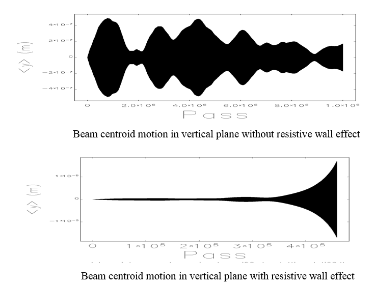
With the application of transverse bunch by bunch feedback, this coupled bunch instability suppresses and stored beam current reach to more than 200mA.
Study of Fast beam ion instability in Indus-2
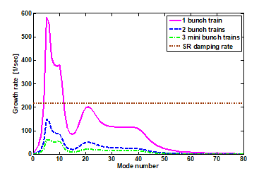
To overcome conventional ion trapping in the storage ring, normally an optimized bunch clearing gap in a single bunch train is provided. However, with this configuration of long bunch filling pattern, a transient phenomenon may develop along the bunch train known as fast beam ion instability (FBII). This could cause transverse dipole motion of the electron bunches, with the amplitude increases in time along the bunch train and that ultimately leads to deterioration in the beam quality. The possibility of FBII in Indus-2 was studied numerically using a simulation code FASTION for single train of 192 bunches. The harmonic number of Indus-2 storage ring is 291 which are the maximum number of RF buckets available for bunch filling. The essential residual gas pressure threshold in the Indus-2 storage ring for developing FBII was determined by comparing the instability growth time with the radiation damping time. The estimation reveals that the average vacuum pressure of ~17 nTorr CO gas at 200 mA beam current and with the reduced electron beam emittance of 45 nm rad may lead to FBII. However, the simulations of FBII were carried out at elevated vacuum pressure of 50 nTorr CO gas. In this configuration, the FBII growth time is estimated to be 0.6 ms in the vertical plane at 2.5 GeV energy. The FBII was studied analytically by another approach using wake function formalism which estimates the wake field offered by an ion beam and using typical instability theory. This approach facilitates study of FBII in presence of multiple gases and multi-train bunch filling pattern. This method estimates FBII growth time of 0.58 ms by analytical means for the same machine configuration used in simulation code FASTION. This shows that the result of wake-field approach agrees well with that of FASTION Simulation. Assuming the situation of FBII in Indus-2, mitigation strategy was evolved. As a mitigation strategy of this instability, the generated ion density in the beam path can be reduced by replacing a single long bunch train into many short bunch trains. Bunch filling pattern was optimized with a constraint that minimum of 17 bunch gaps is required between two adjacent bunch trains for ion clearing mechanism. For a total 192 filled bunches, maximum 5 bunch trains with suitable bunch gaps can be configured. The analysis reveals that two or more bunch train can suppress the FBII effectively even at 50 nTorr vacuum pressure of CO gas in Indus-2. The instability growth rate for three different bunch filling patterns consisting of same number of total filled bunches are shown in figure below, along with the synchrotron radiation damping rate. In single train, there are 192 bunches and 99 bunch gaps. In two train configuration each train consists of 96 bunches and 49 bunch gaps. In three train pattern, each train consist of 64 bunches and 33 bunch gaps.
|
| Multi bunch train filling pattern in storage ring suppressing the growth of the FBII. |
An experiment was conducted to raise vacuum pressure of the storage ring by switching OFF all the sputter ion pumps except at a few sensitive locations. This process could raise the vacuum level to 6.7 nTorr and concurrently no signature of FBII could be detected.
Microtron beam emittance measurement and its optimization for booster
Beam emittance measurement
In a charged particle accelerator, beam, emittance is a very important parameter. There are different methods of beam emittance measurement like pepper pot, single slit method, quadrupole scan method etc. Quadrupole scan method is one of the most commonly used methods for beam emittance measurement for lepton injector systems at medium beam energy range in which the beam is not primarily space-charge dominated.
Beam optimization with new microtron
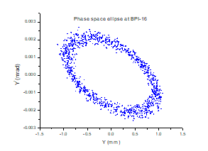
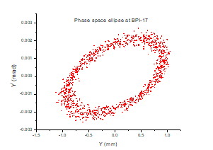
First the beam which is coming out from the new microtron was centred in horizontal as well as in the vertical plane using microtron external channel, VSC, HSC and combined function steering magnet located in the beam transport line-1. Phase space area occupied by the beam is called beam emittance. Beam emittance, which is defined as phase space area occupied by the beam and Twiss parameters measurement was carried out of this new microtron using quadrupole scan method. In the quadrupole scan method, the rms beam size is measured as a function of the strength of one or more quadrupoles situated upstream to a beam profile monitor (BPM) in a beam transfer line. The measured emittance in horizontal and vertical plane is 1.21mm mrad and 4.16 mm mrad respectively. Based on the measured values, new beam optics for TL1 was calculated and applied. With this new optics of TL1, a maximum of 6.5 mA accelerated booster current was achieved.
Up-gradation activity
Pinger magnet
Pinger magnet is a pulsed dipole magnet which deflects the beam in transverse direction and excites betatron oscillations. The pulse width of the magnet is so chosen that the beam deflects only once during a revolution time. After the kick is applied, the evolution of the beam motion is sampled via synchronized turn-by-turn beam position monitors (BPM). From the analysis of turn-by-turn data, the linear and nonlinear beam dynamics studies can be performed in a storage ring. In this way pinger magnet becomes an important diagnostic tool.
In near future, Indus-2 lattice will be equipped with two families of harmonic sextupoles for suppressing the resonance driving terms (RDT) with an aim of increasing the dynamic aperture. However, for proper tuning of harmonic sextupoles, RDT measurement is required. RDT can be determined by harmonic analysis of turn-by-turn BPM data. For this purpose, there is a proposal to install two independent pinger magnets in Indus-2 electron storage ring, one for each horizontal and vertical plane. The specifications of the pinger magnets at peak energy are given in the table below.
Description |
Horizontal |
Vertical |
Deflection angle
(mrad) |
1.5 |
2.0 |
Magnetic Field
(Gauss) |
~525 |
~535 |
Magnet length |
250mm |
250mm |
Pulse width |
< 1 μs |
< 1 μs |
Pulse shape |
Half sine |
Half sine |
In the year 2020, vertical Pinger magnet was installed in short straight section (SS-7) of Indus-2 lattice and in future horizontal pinger magnet will be installed in long straight section (LS-4). Though the facility is not fully automated yet, we captured turn by turn beam position data at 14 BPM’s using vertical pinger magnet in Indus-2. We carried out the data analysis and found that all BPM’s are not synchronised. Further, by Fourier analysis of the data, primary frequency corresponding to betatron tune and coupling were identified. We also used the data for the phase space reconstruction at two beam position monitors those are separated by drift space.
|
Turn by turn data at one of the BPM in Indus-2 captured by exciting the beam in vertical plane |
|
|
FFT of TBT data in vertical plane |
FFT of TBT data in Horizontal plane showing coupling term |
Harmonic Sextupole
Dynamic aperture (DA) is one of the deciding parameters of the low emittance electron storage ring performance. Sufficient DA is required to reach higher injection efficiency as well as good beam lifetime. In low emittance storage rings, dynamic aperture is generally limited due to the high strength of chromaticity correcting sextupoles. In order to enhance the DA, more sextupole magnets are introduced in the dispersion free straight section of the ring lattice, known as “harmonic sextupoles”.
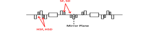
In Indus-2 storage ring, there is a plan for installation of 32 harmonic sextupole magnets in the long straight section of the lattice and those will be powered by two families of power supplies (HSF, HSD). Harmonic sextupole will be useful in increasing the DA in Indus-2 through the suppression of different resonance driving terms (RDT) which are responsible for reducing the DA. Resonance driving terms will be measured first through Fourier transformation of turn by turn beam position data created by a fast one turn pulsed magnet known as pinger magnet.
|
Location of harmonic sextupoles in one of the unit cell of Indus-2 lattice |
In the past, a theoretical analysis of resonance driving terms was carried out using the Hamiltonian approach. The Hamiltonian of the particle in the transverse plane of the storage ring lattice is decomposed into a series of different orders, related to various resonance driving terms (RDTs), 4 chromatic and 5 geometric. The geometric terms are associated with integer resonance Qx, third integer resonance 3Qx, integer resonance Qx, coupling difference resonance Qx-2Qy and coupling sum resonance Qx+2Qy. These terms are responsible for reducing the dynamic aperture for on-momentum particle and they required to be reduced to enlarge the dynamic aperture. Now there are two families of harmonic sextupole and five resonance driving terms. We assign different weight factor to different RDT. The approach for assigning weight factors to different RDTs for optimization is based on the magnitude of individual RDT, sensitivity of the lattice for different RDTs (i.e. the change in RDT with sextupole strength) and input from the results of FMA in presence of chromaticity correcting sextupoles.
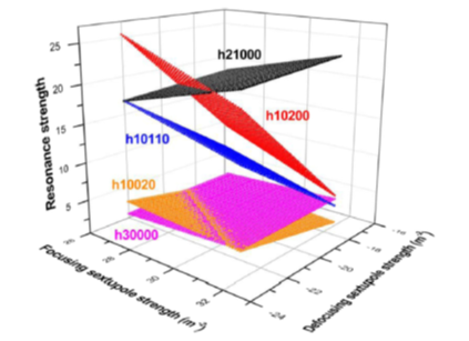
Before energizing the harmonic sextuples in the model we first identified the RDT which is culprit for reducing the dynamic aperture in Indus-2. For it, the harmonic sextupoles were put OFF initially and only chromaticity correcting sextupoles were made ON. The resonance driving terms were calculated for the full range of strength of sextupoles which generates zero to +5 unit of chromaticity. These calculations correlate the RDTs with the strength of sextupoles, i.e. these provide sensitivity of the lattice against different driving terms with sextupole strength. Here two terms, h30000 and h10020 are relatively small in magnitude in the entire range of chromaticity tuning from zero to +5 units, i.e. terms are smaller as well as lattice is not sensitive to these terms for sextupole tuning. Term h21000 is higher in entire range. Terms h10110 and h10200, increases with making chromaticity more positive.
|
Resonance driving terms for different strength of chromaticity correcting sextupoles in Indus-2 for low emittance mode. |
We performed the frequency map analysis (FMA) for Indus-2 lattice to assign the weight factors to different resonance terms. FMA shows the presence of fourth order and one third order resonance in the map. Different fourth order resonances can be excited by the cross terms of resonances discussed above, excited by sextupoles. From FMA plot, it is clear that diffusion coefficient is higher at 4Q x=1. The mode 4Q x is excited by cross terms of third order resonance strength and any resonance line up to third order, which corresponds to RDTs are not there in FMA. Therefore, if prominent third order resonance terms are suppressed by suitable weight, then effect of fourth order resonance due to sextupole also becomes weak. Keeping these points in view, highest weight factor is assigned to the h 21000 in the optimization and h 10110 and h 10200 are kept almost at equal weight factor, lesser than h 21000 and higher than other two.
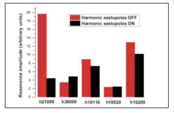
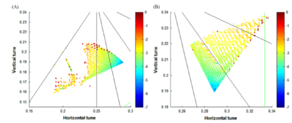
Using above mentioned procedure, maximum weight is assigned to h 21000.The analysis showed us that resonance driving terms are suppressed at optimised strengths of harmonic sextupoles and there is a reasonable enhancement of dynamic aperture for two different working points of Indus-2.
|
Resonance driving terms without and with the harmonic sextupoles. |
|
Frequency map without and with harmonic sextupole magnets for low emittance optics |
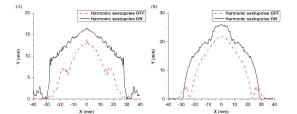
|
Dynamic aperture with and without harmonic sextupoles in Indus-2 (A) low emittance optics (B) Present optics |
Baseline design of storage ring for High Brilliance Synchrotron Radiation Source (HBSRS)
Lattice design for storage ring of HBSRS
To achieve synchrotron radiation brightness more than 1022 [ph/sec.mm2. mrad2. (0.1%BW)], in the photon energy range 10-200 keV from insertion devices, a high brightness synchrotron radiation source (HBSRS) is being studied. A new 6 GeV electron storage ring is capable to provide the required ultra-low beam emittance in pm rad range. To achieve such a low emittance, lattice design studies are performed using advanced concept of hybrid multi-bend achromat and utilising the multi-objective optimization techniques. Based on these studies, a compact baseline lattice is proposed which provides beams with emittance of 150 pm rad in a storage ring circumference of ~ 910 m with following features and constraints:
Magnets: Strength of the dipole up to 0.75 T and quadrupole magnet gradient up to 80 T/m.
Number of available long straight sections are 32
Length of each long straight section is 6 m
Lattice design objective is minimizing Synchrotron Radiation (SR) loss and maximizing Dynamic Aperture for on and off momentum particles
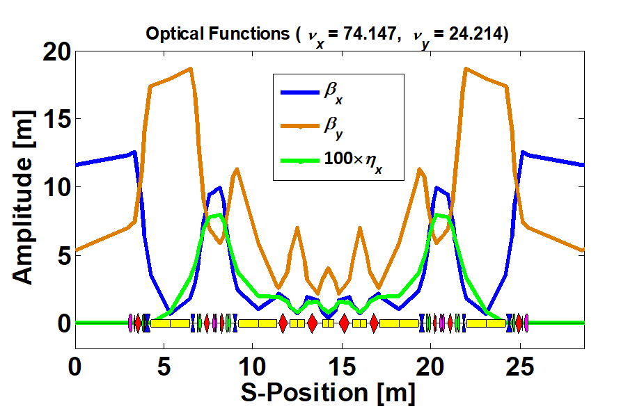
Such a low emittance storage rings results in large negative chromaticities, and for their correction, strong sextupole magnets are used. These makes the beam dynamics nonlinear and ultimately reduces the available aperture, called dynamic aperture available for the stable movement to the beam. Optimization of dynamic aperture is a challenging task, and in this studies a class of multi-objective and multivariable optimisation techniques are used. In order to achieve efficient chromaticity correction, a dispersive bump is generated at the locations of sextupole magnets. The lattice functions for an optimized baseline lattice and tune diagram showing designed betatron tune are shown in the following figure.
Tentative hybrid seven bend achromat lattice of HBSRS producing 150 pm.rad beam emittance. Yellow rectangles show dipole magnets, red & blue- quadrupole magnets and green & magenta- sextupole magnets.
|
| Tune diagram up to fourth order showing designed betatron tune (star mark) |
Lattice design with super-bend in HBSRS
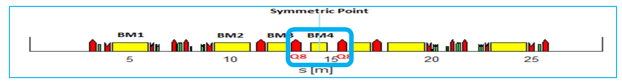
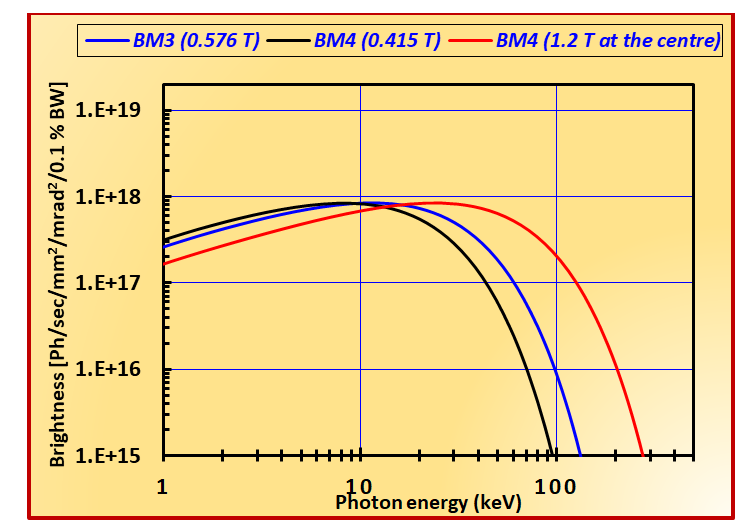
The layout of the magnetic lattice of the HBSRS is shown in figure below. The dipole magnet fields are kept below 0.6 T and with transverse gradient upto 37 T/m. In particular, the magnetic field in dipoles BM3 and BM4 are 0.576 T and 0.415 T respectively. These dipoles emit the synchrotron radiation with critical energies 13.8 keV and 9.9 keV, respectively.
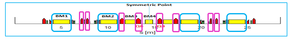
Magnet arrangements in one out of 32 super-periods of HBSRS magnetic lattice. Yellow rectangles are the dipoles, red are the quadrupoles and green are the sextupole magnets. Dipole (BM4) in the rectangular selection (blue colour) is split into three parts with high field (super-bend) in the middle and lower fields on either side parts.
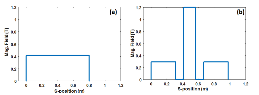
In order to increase the usable energy from the bending magnets, dipole BM4 is split into three parts and their magnetic fields are optimized in such a way that the total bending angle over three parts remains same as without splitting the dipole BM4. The magnetic field over complete dipole BM4 is shown in figure below.
|
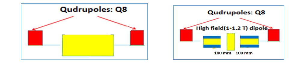
Dipole BM4 (left) and BM4 split into three parts (right) separated by 100 mm with high field 1.2 T at the center and two other parts, with low field 0.3 T & high transverse gradient. |
The variation of magnetic field in dipole magnet BM4 (a) before splitting and (b) after splitting into three parts separated by 100 mm with central high field slice of 1.2 T (super bend).
The magnetic field in the central part is 1.2 T (super-bend) and magnetic field in either side parts is 0.29 T. These three parts are separated by 100 mm to take care of coil protrusions as these magnets are considered as electromagnets. This arrangement increases the number of dipoles from 224 to 288. The overall circumference will increases by ~6.5 m. The calculated brightness with different fields is shown in figure below.
|
Photon beam brightness with photon energy from the dipole magnets with fields: 0.415 T (un-split dipole BM4), 0.576 T (dipole BM3) and 1.2 T (super-bend in BM4). |
Lattice of HBSRS storage ring using longitudinal gradient bend and anti-bend
In a well-designed low emittance storage ring with conventional magnets, there is further scope of reducing the beam emittance and simultaneously improving the nonlinear behaviour of the lattice. An innovative concept for beam emittance reduction is to include anti-bends (ABs) in the focussing quadrupoles. This will help in shaping the slope of the dispersion function inside the main dipole magnets and increases the horizontal damping partition and independently controlling dispersion and beta functions. As a result, it decreases the beam emittance. By varying the magnetic field in the main dipoles to compensate the growth of dispersion beyond the dipole centre also results in reduced beam emittance. This innovative concept is known as longitudinal gradient bend (LGB). However, main advantage comes in the form of reduced sextupole strengths as the dispersion at the sextupole locations is being enhanced. Figure below shows the schematic of magnetic elements in one super period of HBSRS lattice. The LGBs are shown by blue coloured open rectangles and ABs are shown by magenta coloured open rectangles.
Magnet arrangements in one out of 32 super-periods of HBSRS magnetic lattice. Yellow rectangles are the dipoles, red are the quadrupoles and green are the sextupole magnets. The blue open rectangles show the dipoles with longitudinal gradient bends and the reverse bending is included in the focussing quadrupoles (magenta coloured rectangles).
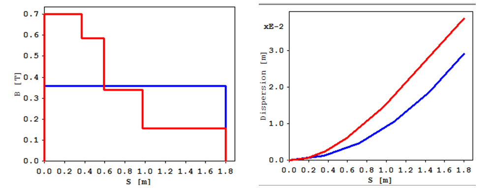
The normal magnetic field in the dipoles BM1 and BM2 is 0.32 T and bending angle of 1.75 deg. For LGB profile optimization the maximum field is considered as 0.7 T. The bending angle was constrained to be same as in normal dipole. Figure below shows the optimized LGB profile over the five-part model of the dipole magnet. The dispersion function in the dipole is low at high field end (0.7 T) and high at low field end (0.15 T). At the exit of the dipole, the dispersion attains its large value in LGB compared to normal dipole. It can further propagate upto the sextupole location to value much larger than the normal one. Due to high field in the LGB, the synchrotron radiation loss will increase.
|
Left Fig: The magnetic field in the dipole with the optimized LGB profile (red) and without LGB profile (blue), Right Fig: variation of dispersion function in dipole with and without LGB. |
In HBSRS lattice, small AB of 0.025° is introduced in shorter length focussing quadrupoles, and 0.05° in longer length focussing quadrupoles. The bending angles of the main dipoles were adjusted to total bending the charged particles by 360°, however absolute bending is increased to 398.4°. This arrangement leads to more synchrotron radiation loss per turn and hence the improved damping of particle oscillations results in reduced beam emittance. By introducing the ABs, the integral of dispersion over entire ring decreases which ultimately minimize the momentum compaction factor. However, the energy spread increases as longitudinal damping partition coefficient also decreases. The comparison of important lattice parameters in baseline lattice and the lattice including LGBs and ABs are given in Table below.
Table 2: Basic lattice parameters in reference lattice and lattice with super-bend in dipole BM4.
|
Reference lattice |
Lattice with LGB and AB |
Units |
| Energy |
6 |
6 |
GeV |
| Absolute bending angle |
360 |
398.4 |
deg |
| Emittance |
148 |
108 |
pm rad |
| Eloss per turn from dipole |
2.375 |
3.16 |
MeV |
| Betatron tune (x, y) |
77.15, 27.20 |
78.14, 26.17 |
|
| Natural Chromaticity (x, y) |
-130, -90 |
-127, -82 |
|
| Energy spread |
9.2e-4 |
1.2e-3 |
|
| Momentum compaction factor |
8.6e-5 |
5.9e-5 |
|
Closed orbit correction scheme for HBSRS storage ring
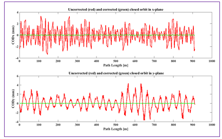
The closed orbit distortion correction scheme consists of a set of 10 beam position monitors (BPMs) and a set of 10 combined function horizontal and vertical corrector magnets (CHVs) per super-period. The distribution of the BPMs and CHVs per super period are shown in figure. The particulars of elements for COD correction in the HBSRS storage ring are given in Table. A typical view of uncorrected and corrected closed orbit over the ring are shown in figure below.
Arrangement of magnetic elements in a super period. Blue, red and green rectangular box represents dipole, quadrupoles and sextupoles magnets respectively. BPM and CHV are shown in black and pink sphere.
Elements for COD correction in HBSRS storage ring
Number of BPMs |
320 |
Number of CHVs |
320 |
Magnetic length of CHVs |
100 mm |
Max strength of CHVs |
± 500 µrad @ 6.0 GeV |
The Closed Orbit Amplification Factor (COAF) is a ratio of rms of COD to rms of errors. The COAF s of transverse misalignments of quadrupoles for linear lattice (without sextupoles) are 138 and 143 in horizontal and vertical planes respectively.
|
A typical view of uncorrected and corrected closed orbit in horizontal and vertical plane |
Study of first turn trajectory correction and closed orbit search in HBSRS lattice
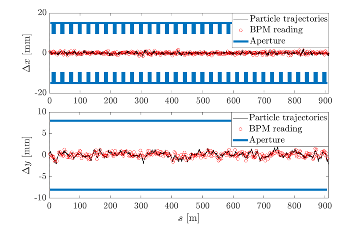
The HBSRS lattice uses strong quadrupoles and sextupoles leading to very small tolerable alignment and calibration errors in practical electron storage ring (ESR), which are practically unachievable with present technology. Both, finding practical tolerable errors and commissioning of such ESR require rigorous simulation study of beam commissioning including injection of electron beam, beam threading to achieve first turn, beam accumulation, closed orbit correction etc. A preliminary study of tolerable errors has been carried out and applied randomly in different magnets of HBSRS. Following an on axis injection scheme, the first turn of electron beam is achieved by optimizing the strength of 320 corrector magnets. Further optimization has been also carried out to achieve beam accumulation and closed orbit correction. The absolute strengths of corrector magnets are well within limits, i.e., below 500 μrad. The achieved first turn and closed orbit after correction, which is within 500 μm in both planes, are shown in figure below.
|
First turn trajectory correction for a given set of random errors |
|
Closed orbit after correction |
Linear optics and coupling correction:
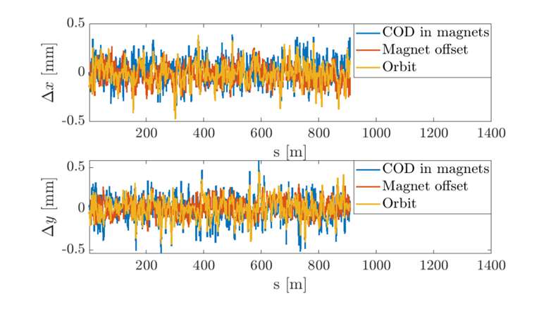
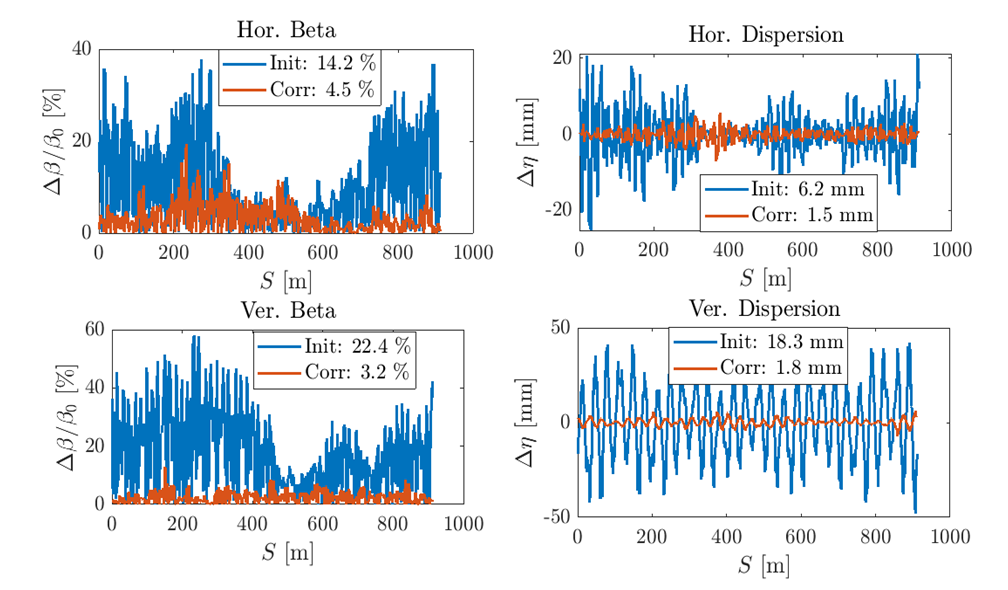
During commissioning, because of various kinds of field and alignment errors, desirable machine parameters deviate and linear and non-linear dynamics deteriorated. The linear optics and coupling errors have been minimized by optimization of strength of quadrupoles and skew quadrupoles in the machine leading to improved dynamic aperture. This will provide improved injection efficiency and beam lifetime. The beta beat and dispersion deviation are presented in figure below.
|
Beta beat and dispersion deviation before and after correction. |
Betatron coupling correction in the HBSRS lattice will leads to very small vertical emittance in the hard X-ray regime. However, operating with such vertical emittance lower than the required value, called diffraction limit, is disadvantageous as it decreases the Touschek lifetime and hence, beam lifetime. A simulation study on the ideal designed HBSRS lattice is carried out to increase the vertical emittance upto ~8 pm.rad by introducing successive closed vertical dispersion bumps (SCVDBs) in the arc sections only. This is achieved by optimizing the skew quadrupole present in the HBSRS lattice, which results substantial increase in Touschek lifetime.
Top-up injection into HBSRS storage ring
In the ring, injection system is designed for transparent top-up operation to maintain almost constant beam current within current stability of 1% with restricts stored beam motion to less than 1/10th of stored beam sizes for SR users. The ring will be operated in two different operating modes:
a. High brightness mode in which either 80% or 2/3rd of total bunches will be filled,
b. Timing mode where only a few bunches will be filled with higher per bunch current and are separated from each other with a long gap.
For transparent top-up operation, booster synchrotron, which will serve as an injector, is designed with ~ 5 nm-rad beam emittance at the final energy of the HBSRS. In the radial plane from inside of storage ring, 6 GeV beam coming from the booster will be injected using thick and thin septum magnets.
For filling of different modes, a bunch train consisting one or more than one bunches from booster will be transferred to the storage ring every 1-2 Hz, until the required current has been established. The beam filling time, top-up interval and refilling time after top-up interval is decided by considering 1 % current stability of stored beam, which is governed by beam lifetime. Generally in high resolution mode frequent beam injection has to be performed due to small beam lifetime.
Two injection schemes are proposed. One is based on a conventional injection kicker scheme in which a compensated bump is generated by four kicker magnets and the other one is based on a single pulsed sextupole magnet. The compensated bump injection scheme will be useful for the initial stage of commissioning and during bill filling. For top-up injection, pulsed sextuploe scheme will be used.
Injection with conventional four dipole kickers
In the ring, all four injection kickers are kept in 1st long straight section. Its schematic diagram is shown in figure below. The main parameters of kickers are shown in Table.
|
Conventional four kicker bump scheme |
Pulsed parameters of injection kicker
Rise Time |
76 μs |
Trapezoidal pulse shape (rise time, flat top time , fall time) |
15076 μs, 2.076 μs, 176 μs |
Deflection |
3.0 mrad |
Good field region |
+/- 15 mm (Horizontal) |
+/- 7 mm (Vertical) |
(DB/ B) within good field region |
1 * 10-3 |
Stability |
0.02 %(shot to shot +flat top ripple) |
Pulse to pulse jitter |
± 0.05% |
Injection with pulse sextupole magnet
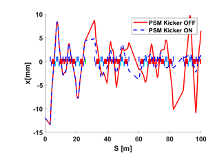
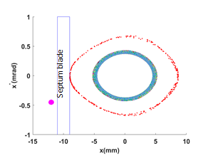
In Pulse Sextupole Magnet (PSM) scheme, the injected beam passes off-axis through pulse sextupole magnet while the stored beam passes through its centre and thus the stored beam will not be affected. Presently location of pulse sextupole magnet is at beginning of 2nd long straight section, which is 25.6 m away from the injection point (IP). The horizontal phase advance of PSM from IP is near to an odd integer multiple of π/4. At the septum exit, offset of injected beam from inner side of central orbit is considered as 12 mm. The first turn trajectory of injected beam in the storage ring with PSM kicker OFF and ON is shown in figure below. The tracking study reveals that, the injection angle plays most significant role in this injection scheme and is optimized to -0.45 mrad for maximum injection efficiency. Figure below shows the phase space of the an injected beam of emittance 5 nm rad tracked through the storage ring for 212 turns corresponding to synchrotron oscillation period of storage ring. Simulation shows capture of injected beam into the storage ring acceptance. The required maximum sextupole gradient is estimated as 4000 T/m2.
|
|
First turn particle trajectory with PSM OFF and ON. PSM is shown in green color rectangle box at beginning of 2nd straight section. |
Phase space of the injected beam tracked for 212 turns. The storage ring acceptance and injected beam is shown in red and magenta color respectively. |
Effect of NEG coating on Resistive Wall Impedance in HBSRS
Non Evaporable Getter (NEG) coating on the inner surface of vacuum chamber has been successfully used to achieve ultra-high vacuum in low emittance storage rings. If a large portion of vacuum chamber is coated with NEG material (electrical conductivity: 1.1×10⁶ Ω-1m-1), it may increase the resistive wall impedance of the ring significantly which may cause parasitic loss and affect beam centroid motion. So the study for optimum value of NEG coating thickness in the design stage is essential for the minimization of the impedances. Simulation studies of longitudinal and transverse impedances with different NEG coating thickness on cylindrical vacuum pipe of 10 mm inner radius and 1 mm thickness of the wall of Aluminium (electrical conductivity: 3.7×10⁷ Ω-1m-1) has been carried out using ImpedanceWake2D computer code. The results of real and imaginary part of longitudinal impedance per unit chamber length at frequencies from 100 Hz to Hz is shown in Figure. The results of real and imaginary part of transverse impedance per unit chamber length at frequencies from 1 Hz to Hz is shown in Figure. These results are matching with the analytical results and also verified by GdfidL computer code.
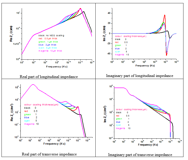
The results show that there is an increase in the longitudinal and transverse impedance at higher frequencies for different thickness of NEG coating. The transition of impedance from Aluminium chamber to NEG coating material chamber are observed at around these frequencies. In this frequency region, the skin depth which becomes comparable to the thickness of NEG coating are ~230 GHz (for 1μm NEG coating thickness), ~57 GHz (for 2μm), ~9 GHz (for 5μm) and ~2 GHz (for 10μm). The results also indicate that at high frequency region where the skin depth is much smaller than the NEG coating thickness, all lines of different NEG coating thickness converge to the same value of impedance.
At very high frequencies i.e. above 10 12Hz, the conductive material behaves almost like as if vacuum chamber without conductive layer resulting in to a decrease in longitudinal and transverse impedance.
Using the real part of longitudinal impedance, loss factor for 3 mm bunch length in HBSRS was estimated and using the loss factor, parasitic loss per unit length of vacuum chamber was estimated and is shown in Figure.
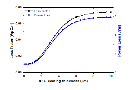
Variation of Loss factor and parasitic loss with NEG coating thickness
The simulation studies indicate that the power loss due to longitudinal impedance does not change significantly for 1μm NEG material coating on inner surface of vacuum chamber. So 1μm NEG material coating thickness may be suitable for HBSRS vacuum chamber.
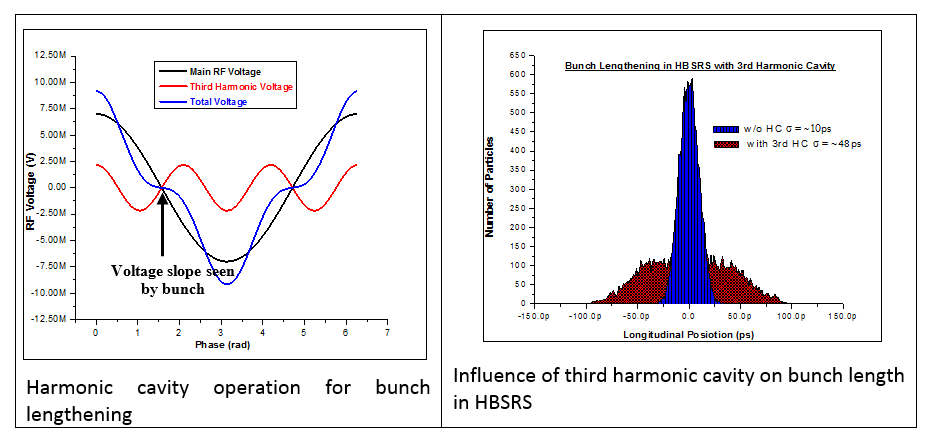
Studies on Higher Harmonic Cavity in HBSRS
In the modern ultra-low beam emmitance synchrotron radiation sources, the beam lifetime is dominated by Touschek scattering among the particles within the bunch. In order to replenish the Touschek scattered, a higher harmonic RF system with frequency 3-4 times of the main RF system is generally proposed to lengthen the bunch and achieve a proportional increase in beam lifetime. The higher harmonic cavity increases the synchrotron frequency spread within the bunch which is helpful in inducing Landau damping that damps longitudinal coupled bunch instabilities. In due course of bunch lengthening, the bunch charge density reduces which is helpful in increasing the single bunch current threshold as well as for low heating of machine components. A higher harmonic cavity can also be used for bunch shortening.
In the ongoing design project lattice for a new high brilliance synchrotron radiation source the Touschek beam lifetime is only ~20 hours at 200mA stored current. In order to improve it, a passively operated (beam driven) 3rd harmonic RF cavity is under consideration as it provides largest bunch lengthening by factor of five, which leads to increase in Touschek lifetime proportionally. A comparison of the basic parameters and the effect of 3rd, 4th and 5th order harmonic cavity on the bunch length is given in Table which show the suitability of third harmonic cavity.
Comparison of higher harmonic cavity parameters and performance for different harmonic Numbers
| Harmonic number(n) |
Frequency (MHz) |
Harmonic RF Voltage(MV) |
Harmonic RF Phase(degree) |
Detuning angle (degree) |
RMS bunch length (mm) |
Bunch lengthening factor |
| 3 |
1500 |
2.16 |
-8.165 |
81.83 |
14.17 |
~5.0 |
| 4 | 2000 | 1.63 | -5.772 | 84.23 | 12.11 | 4.3 |
| 5 | 2500 | 1.31 | -4.498 | 85.50 | 10.76 | 3.8 |
The operation of harmonic cavity is based on the cancelation of the main RF cavity voltage slope at the synchronous phase by properly tuning the phase of harmonic cavity voltage as shown in Figure. If the phase of harmonic cavity is set on the other direction it will lead to bunch shortening. A simulation study to see the effect of third harmonic cavity on bunch length was carried out using multi-bunch particle tracking code MBTRACK. The results of the effect of third harmonic cavity (~1500 MHz) on bunch length is shown in Figure.
 Baseline design for Booster of HBSRS
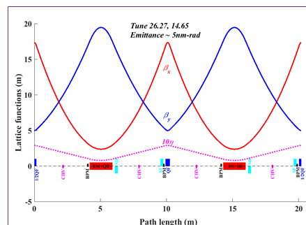
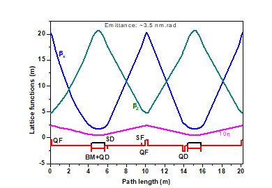
A 6 GeV booster along-with a 200 MeV pre-injector Linac will serve as a top-up injector system for the storage ring of HBSRS. For booster, a modified FODO lattice with 86 unit cells has been proposed. Its unit cell contains a rectangular bending magnet with defocusing gradient, a focusing quadrupole, a pair of focusing and defocusing chromaticity correcting sextupoles. The length and magnetic field strength of bending magnet is chosen to reduce the required RF power at the final beam energy. The unit cell of the booster has been optimized to generate an electron beam with emittance of <5 nm.rad as well as to have a circumference slightly less than the storage ring which will facilitate the use of same tunnel for the storage ring and booster. For flexibility in setting the linear optics, an additional variation of 5% in gradient of the bending magnet is proposed. In booster, beam injection will be carried out using on axis beam injection scheme, afterwards its energy will be increased by using sinusoidal magnet driving current ramp profile. At final energy, beam will be extracted using extraction kicker and septum magnet. Major parameters of booster are shown in the table given below:
Major parameters of booster
Beam energy |
0.2-6 |
GeV |
Circumference |
868.633 |
M |
Rep rate |
1-2 |
Hz |
RF Frequency |
499.75 |
MHz |
Energy loss/turn |
~4.93 |
MeV/turn |
Horizontal and vertical betatron tune |
26.27,14.165 |
|
Emittance |
4.7494 |
nm.rad |
Required RF voltage at 6 GeV |
7.4 |
MV |
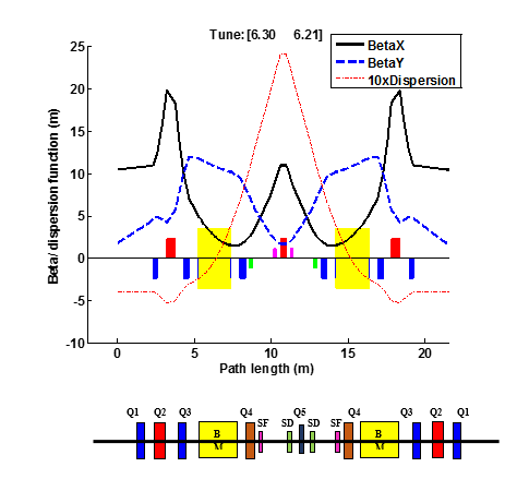
Lattice function of booster for 2 unit cells, QF: Focusing quadrupole, BM+QD: Bending magnet with defocusing gradient, QD: Defocusing quadrupole, SF & SD: Focusing & defocusing chromaticity correcting sextupoles
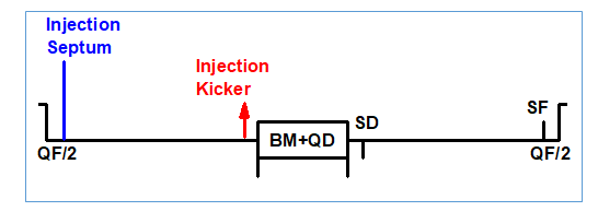
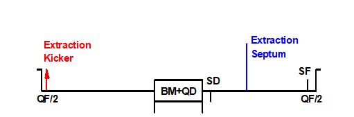
Injection and extraction scheme
The injection and extraction schemes are designed to support two bunch filling modes of HBSRS namely high brightness (beam current will be uniformly distributed in 1000 bunches) and high resolution (different configurations of selected bunches will be uniformly filled). In the figure below, beam injection and extraction scheme are shown, which consists of a fast pulsed kicker and a septum magnet. For two bunch filling modes, flat top of ~2.0 μs are assumed for injection kicker and extraction kicker magnets
|
Schematic diagram of on-axis injection scheme, vertical blue and red lines indicate location of injection septum and kicker magnet respectively. |
|
Schematic diagram for fast beam extraction (without bumper magnet), vertical blue and red lines indicate location of extraction septum and kicker magnet respectively. |
For injection, the inner edge of injection septum is kept at 16 mm from the design orbit. Considering half beam size for 3σ at 200MeV, septum thickness, septum clearance for the beam, a bump of 25 mm is required at the injection septum mouth. For this, required kick of injection kicker is estimated ~ 11.3 mrad.
For extraction, the inner edge of extraction septum is fixed at 16 mm from the design orbit. For extraction, a bump of 22 mm is required at the extraction septum mouth by considering half beam size for 3 at 6 GeV, septum thickness and septum clearance for the beam. Preliminary estimation of power supply reveals that for extraction kick of 1.8 mrad only is possible in technological limits which can generate a bump of ~19 mm only. Therefore, it is proposed to use 3 bumpers to generate an additional bump of ~3 mm.
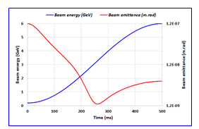
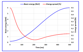
Magnetic field profile for ramping
In booster, it is required to have a proper ramp profile for magnet currents to increase the beam energy. Presently, it is proposed to use a sinusoidal energy ramp profile with repetition rates of 1-2 Hz. In the sinusoidal profile, a sufficient time is available at injection and extraction zones in which the magnetic field variation is negligible. This will be helpful to minimize the effect of eddy current on the beam during injection and extraction. Moreover at the end of ramping, the emittance and energy spread reaches to nearly their equilibrium values as can be seen in the figures below. Therefore, it is not needed to have an additional flat top to stabilize the values at equilibrium.
|
|
Variation of beam emittance during energy ramping |
Variation of beam emittance during energy ramping |
RF voltage in booster
A suitable profile of RF voltage is required for the beam energy ramping keeping the eye on longitudinal beam parameters. At injection, the RF voltage is should be sufficient to accommodate bunch length and energy spread of injected beam within the bucket size of the booster whereas at extraction it should provide a smaller bunch length to minimize injection losses in the storage ring. As the electron beam from the linac has a bunch length of ±0.5 ns and an energy spread of ±0.5 %, RF voltage of 44 kV at injection is estimated to accommodate 2σ values for these parameters. At extraction, the voltage of 7.4 MV is estimated with an over voltage factor of ~1.5 providing a bunch length which is ~3.5 times of the bunch length in the storage ring.
Closed orbit correction scheme
The closed orbit distortion correction scheme consists of 2 Beam Position Monitors (BPMs) giving beam position information in both transverse planes and 2 combined function horizontal and vertical corrector magnets (CHVs). The distribution of the BPMs and CHVs in the booster lattice are shown in figure below. The particular of elements for COD correction are given in Table. A typical view of uncorrected and corrected closed orbit over the ring are shown in figure.
|
Distribution of BPMs and CHVs in the HBSRS booster per unit cell |
Elements of COD correction for HBSRS booster
Number of BPMs |
172 |
Number of CHVs |
172 |
Max strength of CHVs |
± 300 µrad @ 6.0 GeV |
|
A typical view of uncorrected and corrected closed orbit |
Transport line design from booster to storage ring (BTR) for HBSRS
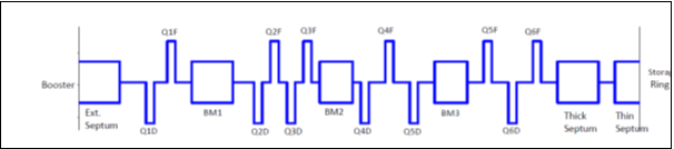
A preliminary studies of beam transport line from booster synchrotron to the storage ring (BTR) has been carried out using computer code TRANSPORT. In the proposed layout, the booster ring is inside the storage ring and has a clear radial distance of 7.0 m relative to the storage ring. The transfer line from booster extraction point to the injection point of the storage ring has length ~ 34 m with effective bending angle of 16.5°. Schematic diagram of the layout of various magnetic elements of BTR transfer line are shown in figure. It includes one 60 extraction septum magnet, three bending magnets (BM1, BM2 and BM3), 12 quadrupoles (6 focussing and 6 defocussing) and injection septum magnet (thick and thin).
|
Layout of booster to storage ring transfer line |
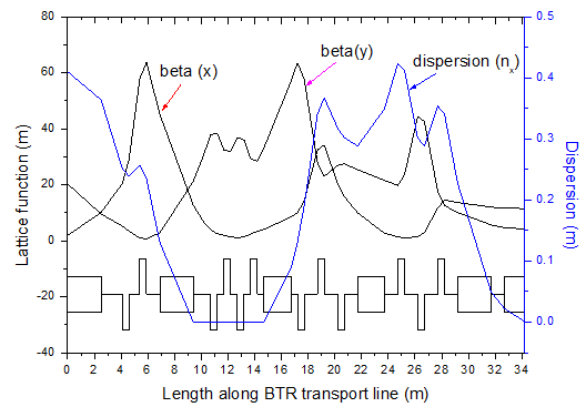
The quadrupoles are used to match the lattice twiss parameters in both the transverse planes and makes the dispersion function and its derivative zero as required at the injection point of the storage ring. The matched lattice twiss parameters along the line are shown in figure. The horizontal dispersion function is below 0.45 m throughout the transfer line. Adequate space has been left for installation of various diagnostic elements and steering magnets in the line.
|
Lattice parameters in the transport line |
CTF-3 design at CERN
CLIC Test Facility-3 (CTF3) is a project of CERN to demonstrate the proof of principle of two beam acceleration scheme, which will be used in future electron positron collider, CLIC. Under DAE-CERN collaboration, optics design of a bunch compressor cum transfer line, namely TL-2 is carried out for CTF3 and the line is shown in figure. This line is able to tune R56 in a very wide range (from -0.25 m to +0.25 m) with suppression of second order aberration T566 in the entire range. Such wide range of tuning and optimization of sextupole scheme to make T566 nearly zero, are some of the important and unique features of this line. On the basis of the optics design, the transport line TL-2 has been installed and commissioned successfully at CERN.
|
Optics design of TL-2 for CTF-3 |
50 keV/700 mA low emittance thermionic electron gun for 10 MeV linac of ARPF
The measured beam emittance of the previously designed 50 keV triode gun was greater than the permissible value to the 10 MeV accelerating structure of Linac-3. Physics design of new 50 keV/700 mA, thermionic, Pierce, planar, diode electron gun has been carried out with the objective of obtaining lower emittance at the input of linac structure. This low emittance gun has been developed, tested and integrated with LEBT on Linac-3. It has increased the accelerated beam current from the linac and improved the performance of the beam delivery system. The design parameters of the low emittance electron gun are listed in Table.
Design specification of low emittance gun for 10 MeV linac
Parameters |
Type/Values |
Type of Gun |
Thermionic, Diode, DC-Pulsed, Pierce planar |
Mode of heating |
Indirect |
Cathode |
Planar (dispenser) , Diameter= 8 mm |
Energy |
50 keV (Fixed) |
Method of generating pulse beam |
Cathode pulsing |
Energy spread |
<= 0.5% |
Peak beam current |
700 mA (space charge mode) |
Beam parameters at the exit of gun in both the planes |
beam radius (1σ) < 2 mm at the entrance of LEBT |
Unnormalized rms emittance < 10 mm-mrad at the prebuncher location |
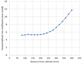
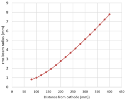
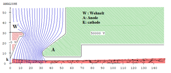
In the simulation, shape and size of presently used dispenser cathode assembly of electron gun for 10 MeV linac is used as a starting point. A diode gun having Pierce configuration is optimized using EGUN code to produce slightly convergent beam inside the space between cathode and anode. In the simulation, dimensions of the gun components are magnified ten times and beam parameters at 50 keV beam energy are simulated at a distance of 20 mm from the anode using 500 rays. These simulated beam parameters are then taken as an input to another EGUN file, having only drift space after the anode. The effect of space charge forces on emittance of the beam in drift space (upto 400 mm from cathode) has been simulated with this method. The variation of beam parameters at 600 mA beam current along the beam axis is shown in figure below.
|
|
Growth of un-normalised rms emittance along beam axis at 600 mA |
RMS beam radius along beam axis at 600 mA |
Beam trajectories obtained from EGUN code upto 150 mm from cathode for the optimized geometry is shown in figure below.
|
Beam trajectory upto 150 mm from cathode(all dimensions are in mm) |
Measured characteristic plots
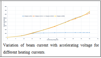
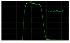
The gun has been tested on a test bench capable of measuring beam parameters at pulse repletion rate of 1 Hz. At 1.5A heating current to the cathode, maximum 650 mA beam current has been measured at 50 kV accelerating voltage, operating at pulse repetition rate of 1 Hz on the test bench. Measured DSO waveform of beam current (pulse width=10 μs) is shown in figure. The measured beam sizes at 650 mA in both the planes are ≈20 % higher compared to simulated values. Presently, emittance measurement using pepper pot technique is underway on the test bench.
|
Measured beam current at 50 keV |
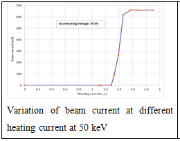
The measured characteristic plots of the gun are shown in figure below.
|
|
Variation of beam current at different heating current at 50 keV |
Variation of beam current with accelerating voltage for different heating currents. |
The measured perveance of the gun matches with simulated data using EGUN code within 10 %. Presently, the electron gun is routinely operated at 50 keV/600 mA beam current in linac 3 with repetition rate of 300 Hz.
HBNI activities
APS provides strong impetus to pursue M. Tech. and Ph. D. programme in the field of accelerator physics. Details are listed below.
Group member |
Programme |
Title of thesis |
Year of completion |
Pradeep Kumar |
Ph. D. |
Studies Of Beam Lifetime In Synchrotron Radiation Source Indus-2 |
2015 |
Ali Akbar Fakhri |
Ph. D. |
Study Of Beam Injection, Beam Optics And Insertion Devices For Synchrotron Radiation Source: A Case Study Of Indus-1 And Indus-2 |
2017 |
Riyasat Husain |
Ph. D. |
Optimization And Modelling Of Storage Ring Lattices: A Case Study Of Indus-2 Storage Ring |
2019 |
Saroj Kumar Jena |
Ph. D. |
Optimization Of A Multi Bunch Train Filling Pattern For The Suppression Of Beam Ion Instability In Electron Storage Ring: Case Study Of Indus-2 |
2020 |
Abdurrahim |
Ph. D. |
Lattice Optimization Of Electron Storage Rings For Quasi-isochronous Configuration |
Continuing
|
Suraj Prakash |
M. Phil. |
Numerical Optimization Of Longitudinal Magnetic Field Profiles Of A Dipole In A Low Emittance Lattice Cell |
2021 |
Monika Rana |
M. Tech. |
Numerical Simulation Of 20 keV/100 mA DC Thermionic Electron Gun For Testing Photon Absorbers Of Synchrotron Radiation Source |
Continuing
|
Publications
A. Journal Article
- Husain R., Prakash S., Ghodke A.D.
Betatron coupling measurement and optimization in Indus-2 storage ring
Review of Scientific Instruments, Vol. 92, May. 2021
- Jena S.K., Fakhri A. A., Ghodke A. D., Senecha V.K.,
Investigation of fast beam-ion instability (FBII) in wake function formalism for the Indus-2 storage ring. Nuclear Inst. and Methods,
in Physics Research A, Vol. 919, p. 113-118, Mar. 2019
- Husain R., Ghodke A.D.
Constrained multi-objective optimization of storage ring lattices,
Nuclear Inst. and Methods in Physics Research A, Vol. 883, p. 151-158, Mar. 2018
- Husain R., Ghodke A.D.
Analysis and correction of the linear optics errors, and operational improvements in the Indus-2 storage ring,
Chinese Phys. C, Vol. 41, no. 8, Aug. 2017
- Jena S.K. ,Ghodke A.D., Senecha V.K.
Simulation of fast beam ion instability (FBII) in Indus-2 and its experimental observation,
Journal of Instrumentation, Vol. 12, Nov. 2017
- Sinhamahapatra D., Haridas G., Kumar P., Ghodke A.D., Tiwari M.K., Hannurkar P.R.
Synchrotron radiation absorbed dose rate measurement at BL-16 beamline of Indus-2
Indian Journal of Pure and Applied Physics, Vol. 54, p. 259-262, Apr. 2016
- Kumar Pradeep, Singh G., Ghodke A. D. , Vaishnav H., Singh P.,
Dependence of loss rate of electron due to elastic gas scattering on the shape of vacuum chamber ,
VACUUM 120, 67 (2015)
- Sharma Amalendu, Tyagi Deepak Kumar and Ghodke A. D.,
Optimization of harmonic sextupoles in Indus-2 electron storage ring,
Nuclear Instruments and Methods in Physics Research A, 782 (2015)
- Fakhri Ali Akbar , Kant Pradeep, Singh Gurnam and Ghodke A. D.,
An analysis of double bend achromat lattice,
Review of Scientific Instruments, 86, 0333304 (2015)
- Fakhri Ali Akbar , Kant Pradeep, Singh Gurnam and Ghodke A. D.,
Beam emittance reduction during operation of Indus-2,
Review of Scientific Instruments, 86, 0333304 (2015)
- Jena S. K., Husain Riyasat, Gandhi M. L., Agrawal R. K., Yadav S., Ghodke A. D.,
Beam based alignment and its relevance in Indus-2,
Review of Scientific Instruments. 86, 093303 (2015)
- Jena S. K., Ghodke A. D.,
Observation and mitigation of ion trapping in Indus-2,
PRAMANA- Journal of physics Vol. 85, No. 6 (2015)
- Husain, Riyasat, Ghodke A. D., Singh G.,
Optimal placement of the magnets in Indus-2 storage ring,
Chinese Phys. C, Vol. 39(3) (2015).
- Abdurrahim & Ghodke A. D.,
Effect of undulators on the stored electron beam of Indus-2,
Chinese Physics C Vol. 39 (7) (2015)
- Saini R.S., Tyagi Y., and Puntambekar T. A.,
Enhancing the Accelerated Beam Current in the Booster Synchrotron by Optimizing the Transport line Beam Propagation.
PRAMANA- Journal of physics, 2015
- Jena S. K., Yadav S., Agrawal R. K., Ghodke A. D., Fatnani P. & Puntambekar T. A.,
Stabilization of betatron tune in Indus-2 storage ring,
Chinese Physics C Vol. 38(6) (2014)
- Fakhri Ali Akbar, Prajapati S. K., Ghodke A. D. and Singh Gurnam,
Studies of beam injection with a compensated bump and uncompensated bump in a synchrotron,
Review of Scientific Instruments, 84, 083303 (2013)
- Sharma Amalendu, Singh P., Abdurrahim, Ghodke A. D. and Singh Gurnam,
Analytical expressions of transfer functions for a hard edge dipole magnet using a basic geometrical approach ,
Physical Review Special Topics- Accelerators and Beams, 16, 014001 (2013)
- Kumar Pradeep, Ghodke A. D. & Singh G.,
Beam lifetime measurement and analysis in Indus-2 electron storage ring,
PRAMANA- Journal of physics., 80(5), 855 (2013)
- Kumar Pradeep, Ghodke A. D., Karnewar A.K., Holikatti A. C., Yadav S., Puntambekar T.A., Singh G. & Singh P.,
Measurements of aperture and beam lifetime using movable beam scrapers in Indus-2 electron storage ring,
Review of Scientific Instruments. 84, 123301 (2013)
- Husain Riyasat, Ghodke A. D., Yadav S., Holikatti A. C., Yadav R. P., Fatnani P., Puntambekar T. A. & Hannurkar P. R.,
Measurement, analysis and correction of the closed orbit distortion in Indus-2 synchrotron radiation source,
PRAMANA- Journal of physics., 80, 2 (2013)
- Fakhri Ali Akbar , Ghodke A. D. and Singh Gurnam,
Effect of Wavelength Shifter in Indus-1,
Nuclear Instruments and Methods in Physics Research A, 613 (2010)
- Ghodke A. D., Husain Riyasat, Kumar P., Yadav S. & Puntambekar T. A.,
Measurement of parameters in Indus-2 synchrotron radiation source,
Review of Scientific Instruments. 83, 103303 (2012)
- Jain V.K., Bhandarkar U.V., Yadav S., Joshi S. C., Ghodke A. D., Lad M., Hannurkar P. R.,
Estimation of higher order modes of Indus-2 RF cavity using combined electromagnetic-thermal-structural simulations,
Nuclear Instruments and Methods in Physics Research A, 612, (2010).
- Sharma Amalendu, Abdurrahim, Ghodke A. D. and Singh Gurnam,
Optics design and second order longitudinal dispersion minimization in a bunch compressor transfer line for CTF3,
Nuclear Instruments and Methods in Physics Research A, 602, Issue 2, (342-351), (2009)
- Ghodke A. D., Husain Riyasat, Singh G.,
Indus-2 commissioning team, Progress in Commissioning of Indus-2,
ICFA, Beam Dynamics Newsletter No.-41, Dec. (2006)
- Singh G.,
et.al, Commissioning status of Indus-1 SR facility,
Indian Journal of Pure & Applied Physics, 39, (2001)
- Angal-Kalinin D., Singh G.,
Emittance measurements of microtron beam,
Indian Journal of Pure and Applied Physics, 38 (2000)
- Sahoo G. K. and Singh G. ,
Design studies of Indus-2 storage ring lattice using the code ESRO,
Indian Journal of Pure & Applied Physics, 37 (1999)
- Bhawalkar D.D., Singh G. & Nandedkar R. V.,
Synchrotron Radiation Source INDUS-1 and INDUS-2, ,
Pramana 50 (1998)
- Singh G., Angal D., Singh B. and Kant P.,
Synchrotron Radiation Source Indus-2,
Indian Journal of Pure and Applied Physics, 35 (1997)
- Ramamurthi S. S. & Singh G. ,
Status of Indus-1 SR source,
Nuclear Instrumentation Methods A 359 (1992)
- Angal D., Singh G. and Ramamurthi S. S.,
Design of transfer lines for Indus-1,
Indian Journal of Physics 65 A (6), (1991)
- Singh B., Singh G. and Ramamurthi S. S.,
Injection into the synchrotron for Indus-1 and Indus-2,
Indian Journal of Physics 65 A (6), (1991)
- Sahoo G.K., Singh G. and Ramamurthi S. S.,
Variation of beam emittance during acceleration cycle of the synchrotron for Indus-1 and Indus-2,
Indian J Physics 65 A (5), (1991)
- Singh G., Sahoo G.K. and Ramamurthi S. S.,
Spectral brilliance of a weak focusing electron storage ring for synchrotron radiation,
Indian Journal of Physics 62A (1988)
- Sahoo G.K., Singh G. and Ramamurthi S. S.,
Beam lifetime calculations for an electron storage ring for synchrotron radiation,
Indian journal of physics, 62A (1988)
B. Conference papers
- Kant P., Fakhri A.A., Ghodke A.D.
Beam Lifetime Studies in Booster of HBSRS,
Indian Particle Accelerator Conference , VECC, Kolkata , Mar., 22-25, 2022
- Prakash S., Husain R., Jain R., Ghodke A.D.
Beam based calibration of beam position monitors and corrector magnets in Indus-2 storage ring
Indian Particle Accelerator Conference , VECC, Kolkata , Mar., 22-25, 2022
- Husain R., Prakash S., Kant P., Ghodke A.D.
Beam dynamics with anti-bend and super-bend in low emittance storage ring ,
Indian Particle Accelerator Conference , VECC, Kolkata , Mar., 22-25, 2022
- Mishra D.A., Dutta S., Rao K.V., Prasad M., Mohania P., Baxy D., Mahawar A., Namdeo R.K., Singh K.A., Babbar L.K., Holikatti A.C., Jain R., Veerbhadraiah T., Sharma S., Vishwakarma S.C., Jena S.K., Yadav S., Fakhri A.A., Saini R.S., Kant P., Maheshwari P., Kumar K.V., Jana P.K., Das S., Goswami S.G., Ghodke A.D., Lad M., Dwivedi J., Puntambekar T.A.
Design and performance study of new RF cavity for 20 MeV Injector Microtron,
Indian Particle Accelerator Conference , VECC, Kolkata , Mar., 22-25, 2022
- Kumar P., Abdurrahim, Tyagi D.K., Ghodke A.D.
Effect of Non Evaporable Getter (NEG) coating on Resistive Wall Impedances in ultra-low emittance electron storage ring,
Indian Particle Accelerator Conference , VECC, Kolkata , Mar., 22-25, 2022
- Kumar P., Abdurrahim, Tyagi D.K., Ghodke A.D.
Estimations of RF parameters during injection and beam acceleration in medical Proton Synchrotron,
Indian Particle Accelerator Conference , VECC, Kolkata , Mar., 22-25, 2022
- Jena S.K., Husain R., Fakhri A.A., Ghodke A.D.
Fast Beam Based Alignment procedure in High Brilliance Synchrotron Radiation Source,
Indian Particle Accelerator Conference , VECC, Kolkata , Mar., 22-25, 2022
- Jena S.K., Prasad M., Kumar K.V., Sindal B., Abdurrahim, Kumar P., Fakhri A.A., Ghodke A.D., Yadav D.P.
Ion Clearing Studies for Dipole Chamber of Indus-1 Storage Ring,
Indian Particle Accelerator Conference , VECC, Kolkata , Mar., 22-25, 2022
- Husain R., Ghodke A.D.
Lattice design of high brightness synchrotron radiation source with practical requirement of drift spaces for installing various components,
Indian Particle Accelerator Conference , VECC, Kolkata , Mar., 22-25, 2022
- Kumar P., Abdurrahim, Tyagi D.K., Ghodke A.D.
Momentum acceptance and Touschek beam lifetime estimations in ultra-low emittance electron storage ring,
Indian Particle Accelerator Conference ,
VECC, Kolkata , Mar., 22-25, 2022
- Fakhri A.A., Kant P., Ghodke A.D.
Non-Linear Beam Dynamics Studies for Booster Lattice of High Brilliance Synchrotron Radiation Source,
Indian Particle Accelerator Conference , VECC, Kolkata , Mar., 22-25, 2022
- Prakash S., Husain R., Ghodke A.D.
Numerical optimization of longitudinal magnetic field profile in a dipole for emittance reduction in electron storage ring,
Indian Particle Accelerator Conference , VECC, Kolkata , Mar., 22-25, 2022
- Meena V.K., Fakhri A.A., Ghodke A.D.
On-axis Injection Scheme for Booster Synchrotron of High Brilliance Synchrotron Radiation Source,
Indian Particle Accelerator Conference , VECC, Kolkata , Mar., 22-25, 2022
- Rana R., Yadav R.P., Fatnani P., Yadav S., Husain R.
SOFB operation and performance assessment towards orbit stability in Indus-2 SRS,
Indian Particle Accelerator Conference , VECC, Kolkata , Mar., 22-25, 2022
- Rana M., Radheshyam P., Ghodke A.D., Sindal B., Joshi S., Yadav D.P.
Simulation of 20 keV/100 mA strip electron gun for testing photon absorbers,
Indian Particle Accelerator Conference , VECC, Kolkata , Mar., 22-25, 2022
- Meena V.K., Fakhri A.A., Ghodke A.D.
Strategy for First Turn Beam Circulation in High Brilliance Synchrotron Radiation Source,
Indian Particle Accelerator Conference , VECC, Kolkata , Mar., 22-25, 2022
- Abdurrahim, Kumar P., Ghodke A.D.
Study of Single Bunch Instabilities in High Brightness Synchrotron Radiation source ,
Indian Particle Accelerator Conference , VECC, Kolkata , Mar., 22-25, 2022
- Tyagi D.K., Kumar P., Husain R., Ghodke A.D.
Analysis of turn-by-turn BPM data at Indus-2 electron storage ring,
Indian Particle Accelerator Conference , VECC, Kolkata , Mar., 22-25, 2022
- Ghodke A.D.
Operational status of Indus accelerator facilities at RRCAT and planning of new high brightness light source in India,
National Symposium on Radiation Physics (NSRP-22) , New Delhi, Nov., 8-10, 2019
- Ghodke A.D., Radheshyam P., Fakhri A.A., Kumar P., Husain R., Abdurrahim, Jena S.K., Kant P., Meena V.K., Tyagi D.K.
Physics design study for proposed high brightness synchrotron radiation source (HBSRS) in India,
Indian Particle Accelerator Conference (InPAC) , New Delhi, Nov., 18-21, 2019
- Fakhri A.A., Kant P., Ghodke A.D.,
Beam emittance reduction in Indus-2 and lattice upgrade studies,
Asian Forum for Accelerators and Detectors , New Delhi, Feb., 14-16, 2019
- Husain R., Ghodke A.D.,
Betatron coupling measurement and its correction in Indus-2 storage ring ,
Indian Particle Accelerator Conference (InPAC) , New Delhi, Nov., 18-21, 2019
- Kumar P., Tyagi D.K., Ghodke A.D.,
Coupled bunch beam instability due to Resistive wall of vacuum chamber and its cure in High Brilliance Synchrotron Radiation Source.,
Indian Particle Accelerator Conference (InPAC) , New Delhi, Nov., 18-21, 2019
- Kant P., Fakhri A.A., Ghodke A.D.,
Effect of eddy current induced sextupole during ramping in booster synchrotron of HBSRS,
Indian Particle Accelerator Conference (InPAC) , New Delhi, Nov., 18-21, 2019
- Kant P., Fakhri A.A., Ghodke A.D.,
FODO lattice for booster of High Brilliance Synchrotron Radiation Source,
Indian Particle Accelerator Conference (InPAC) , New Delhi, Nov., 18-21, 2019
- Abdurrahim, Fakhri A.A., Ghodke A.D., Banerjee A.
Beam Dynamics Studies in Presence of Superconducting Wavelength Shifter for Indus-2
Indian Particle Accelerator Conference (InPAC) , New Delhi, Nov., 18-21, 2019
- Abdurrahim, Ghodke A.D., Banerjee A.
Study of Low Momentum Compaction Factor Optics and Its Implementation in Indus2
Indian Particle Accelerator Conference (InPAC) , New Delhi, Nov., 18-21, 2019
- Jena S.K., Fakhri A.A., Ghodke A.D., Senecha V.K.,
Ion-beam interaction in electron storage ring of HBSRS,
Indian Particle Accelerator Conference (InPAC) , New Delhi, Nov., 18-21, 2019
- Husain R., Ghodke A.D.,
Linear lattice design studies of high brightness synchrotron radiation source (HBSRS),
Indian Particle Accelerator Conference (InPAC) , New Delhi, Nov., 18-21, 2019
- Fakhri A.A., Kant P., Yadav S., Deep A., Rana R., Kumar K.V., Husain R., Prajapati S.K.
Low emittance optics optimization during operation of Indus-2,
Indian Particle Accelerator Conference (InPAC) , New Delhi, Nov., 18-21, 2019
- Tyagi D.K., Kumar P., Ghodke A.D.
Optimization of higher harmonic RF cavity parameters for enhancing the Touscheck beam lifetime in the storage ring of HBSRS,
Indian Particle Accelerator Conference (InPAC) , New Delhi, Nov., 18-21, 2019
- Kumar P., Ghodke A.D., Yadav S., Arora R.K., Deep A., Lad M., Puntambekar T.A.
Simulation study and measurement of longitudinal coupled bunch instabilities and its cure using longitudinal bunch by bunch feedback system in Indus-2,
Indian Particle Accelerator Conference (InPAC) , New Delhi, Nov., 18-21, 2019
- Jena S.K., Sahu T.K., Nayak M.K., Haridas G., Fakhri A.A., Ghodke A.D., Senecha V.K.
Detection of trapped ions by measuring bremsstrahlung photons in Indus-2,
National Symposium on Radiation Physics (NSRP-22) , New Delhi, Nov., 8-10, 2019
- Ghodke A.D., Fakhri A.A., Kumar P., Husain R., Abdurrahim, Jena S.K., Kant P., Tyagi D.K., Meena V.K.
Beam dynamical considerations for high brilliance synchrotron radiation source (HBSRS),
Indian Particle Accelerator Conference (InPAC) , Indore, Jan., 9-12, 2018
- Meena V.K., Husain R., Fakhri A.A., Ghodke A.D.
Alignment tolerances of the quadrupole magnets and closed orbit correction scheme in low emittance storage ring ,
Indian Particle Accelerator Conference (InPAC) , Indore, Jan., 9-12, 2018
- Merh B.N., Kutubuddin S., Chauhan A., Jena S.K., Agrawal R.K., Fatnani P.
Automation of beam based alignment for Indus-2,
Indian Particle Accelerator Conference (InPAC) , Indore, Jan., 9-12, 2018
- Jena S.K., Meena V.K., Fakhri A.A., Ghodke A.D.
Beam injection with a pulsed sextupole kicker for low emittance electron storage ring,
Indian Particle Accelerator Conference (InPAC) , Indore, Jan., 9-12, 2018
-
Fakhri A.A., Kant P., Ghodke A.D.
Modification of Indus-2 achromat, for installation of insertion devices,
Indian Particle Accelerator Conference (InPAC) , Indore, Jan., 9-12, 2018
-
Prajapati S.K., Fakhri A.A., Ghodke A.D.
Modified scheme of beam energy ramping for booster,
Indian Particle Accelerator Conference (InPAC) , Indore, Jan., 9-12, 2018
-
Sheth S.S., Sheth Y.M., Fakhri A.A., Prajapati S.K., Baxy D.
Nonlinear Reference Profile Generator for Quadrupole Supplies of Booster Synchrotron,
Indian Particle Accelerator Conference (InPAC) , Indore, Jan., 9-12, 2018
-
Kant P., Fakhri A.A., Ghodke A.D.
Studies of beam emittance variation during ramping in booster of low emittance electron storage ring,
Indian Particle Accelerator Conference (InPAC) , Indore, Jan., 9-12, 2018
-
Kumar P., Sinhamahapatra D., Ghodke A.D.
Effect of intra-beam coulomb scattering on beam parameters in ultra-low emittance electron storage ring
Indian Particle Accelerator Conference (InPAC) , Indore, Jan., 9-12, 2018
-
Husain R., Ghodke A. D.
Calibration and restoration of low emittance beam optics in Indus-2 storage ring
Indian Particle Accelerator Conference (In PAC), Indore, Jan. 9-12, 2018
-
Kumar P., Ghodke A.D.
Vertical beam size correction strategy during row phase change of APPLE-II undulator in Indus-2
Indian Particle Accelerator Conference (InPAC), Indore, Jan., 9-12, 2018
-
Abdurrahim, Kumar P., Ghodke A.D.
Beam dynamics effect of APPLE-II undulator on Indus-2 beam
Indian Particle Accelerator Conference (InPAC), Indore, Jan., 9-12, 2018
-
Tyagi D. K., Ghodke A. D.
Beam dynamics with pinger magnet in Indus-2 electron storage ring
Indian Particle Accelerator Conference (InPAC), Indore, Jan., 9-12, 2018
- Husain Riyasat, & Ghodke A. D.,
Indus-2 lattice optimization using multi-objective optimization algorithm
Indian Particle Accelerator Conference (InPAC), Mumbai, Dec 21-24, 2015.
- Husain Riyasat, Jena S. K., Meena V. K., Kant P. K. & Ghodke A. D.
Beta beat correction and improvement in Indus-2 storage ring performance
Indian Particle Accelerator Conference (InPAC), Mumbai, Dec 21-24, 2015.
- Abdurrahim & Ghodke A. D. et.al.
Beam Dynamics Studies during Commissioning of Two Undulators in Indus-2
Indian Particle Accelerator Conference (InPAC), Mumbai, Dec 21-24, 2015
- Kumar Pradeep, Ghodke A. D., Singh G. & Singh
P.Effect of RF phase modulation on longitudinal parameters in Indus-2 electron storage ring
Indian Particle Accelerator Conference (InPAC), VECC, Kolkata, Nov. 19-22, 2013
- Saini R. S. and Ghodke A. D.
Beam optics design of electron beam transport line from proposed injector linac to the booster synchrotron.
Indian Particle Accelerator Conference (InPAC), VECC, Kolkata, Nov. 19-22, 2013
- Tyagi Y.*, Saini R.S., Ghodke A. D. & Singh Gurnam
Development of a Transverse beam emittance and Twiss parameters measurement system for Transport line-1
Indian Particle Accelerator Conference (InPAC), VECC, Kolkata, Nov. 19-22, 2013
- Fakhri Ali Akbar & Ghodke A. D.
Electron Beam Optics of Indus-2 in Presence of Insertion Devices
Indian Particle Accelerator Conference (InPAC), VECC, Kolkata, Nov. 19-22, 2013
- Sharma Amalendu and Ghodke A. D.
Application Program Development and its use in Indus-2
Indian Particle Accelerator Conference, VECC (InPAC), Kolkata, Nov. 19-22, 2013
- Sharma Amalendu, Singh P., Ghodke A. D. & Singh Gurnam
CSR studies for transfer line-2 at CTF3, CERN
Indian Particle Accelerator Conference (InPAC), VECC, Kolkata, Nov. 19-22, 2013
- Husain Riyasat & Ghodke A. D.
Orbit response matrix analysis in Indus-2 at 2.5 GeV
Indian Particle Accelerator Conference (InPAC), VECC, Kolkata, Nov. 19-22, 2013
- Husain Riyasat, Vats D. K. & Ghodke A. D.
Chromaticity measurement during beam energy ramp in Indus-2
Indian Particle Accelerator Conference (InPAC), VECC, Kolkata, Nov. 19-22, 2013
- Jena S., Fakhri Ali Akbar & Ghodke A. D.
Beam Dynamics Requirement for Proposed Booster Extraction Septum Magnet
Indian Particle Accelerator Conference (InPAC), VECC, Kolkata, Nov. 19-22, 2013
- Kant Pradeep, Fakhri Ali Akbar & Ghodke A. D.
Exploration of tune point for Booster
Indian Particle Accelerator Conference (InPAC), VECC, Kolkata, Nov. 19-22, 2013
- Kant Pradeep, Fakhri Ali Akbar & Ghodke A. D.
Field error tolerances of eddy current thin septum for Indus-2
Indian Particle Accelerator Conference (InPAC), VECC, Kolkata, Nov. 19-22, 2013
- Fakhri Ali Akbar, Kant P., Ghodke A. D. & Singh G.
Low emittance electron beam optics commissioning in Indus-2
Indian Particle Accelerator Conference (InPAC), IUAC, Delhi, Feb., 15-18, 2011
- Saini R. S., Ghodke A. D. and Singh Gurnam.
Scheme for Beam Energy Spread Measurement of 20 MeV Microtron.
Indian Particle Accelerator Conference (InPAC), IUAC, Delhi, Feb., 15-18, 2011
- Saini R. S., Biswas B.*, Pant K. K., Ghodke A. D. & Singh Gurnam.
Electron Beam Optics Design of Variable Energy Beam Transport Line for a Tunable Infra-Red Free Electron Laser at RRCAT.
Indian Particle Accelerator Conference (InPAC), IUAC, Delhi, Feb., 15-18, 2011
- Prajapati Sanjay Kumar, Fakhri Ali Akbar, Ghodke Ajay. D. and Singh Gurnam
Modified Bunch Filling Scheme for Indus-2
Indian Particle Accelerator Conference (InPAC), IUAC, Delhi, Feb., 15-18, 2011
- Singh G., et al.
Status of Indus-2 Synchrotron Radiation Source
Indian Particle Accelerator Conference (InPAC), IUAC, Delhi, Feb., 15-18, 2011
- Husain Riyasat, Ghodke A. D. & Singh Gurnam
Exploring Storage Ring Lattices, Indus-1 & Indus-2
Indian Particle Accelerator Conference (InPAC), IUAC, Delhi, Feb., 15-18, 2011
- Husain Riyasat, Kant Pradeep, Ghodke A. D. & Singh Gurnam
Beam Dynamics with New Booster Dipoles
Indian Particle Accelerator Conference (InPAC), IUAC, Delhi, Feb., 15-18, 2011
- Abdurrahim, Jain V. K., Ghodke A. D. and Singh Gurnam.
Optimization of Ti Coating Thickness for Indus-2 Injection Kicker Ceramic Chamber
Indian Particle Accelerator Conference (InPAC), IUAC, Delhi, Feb., 15-18, 2011
- Jena Saroj, Ghodke A. D. & Singh G.
Study of Ion trapping phenomena in Indus-2 storage ring
Indian Particle Accelerator Conference (InPAC), IUAC, Delhi, Feb., 15-18, 2011
- Saini R. S., Biswas B., Pant K. K., Ghodke A. D. & Singh Gurnam
Electron beam optics design of variable energy beam transport line for a tunable infra-red free-electron laser at RRCAT
Indian Particle Accelerator Conference (InPAC), IUAC, Delhi, Feb., 15-18, 2011
- Kumar Pradeep, Ghodke A. D. & Singh Gurnam
Studies of beam lifetime in Indus-2 electron storage ring
Indian Particle Accelerator Conference (InPAC), IUAC, Delhi, Feb., 15-18, 2011
- Singh Gurnam, Ghodke A. D. & et al,
Current status and improvements planned in Indus‐2
Indian Particle Accelerator Conference (InPAC), RRCAT, Indore, Feb 10-13, 2009
- Saini R. S., Ghodke A. D. & Singh Gurnam
Beam transmission in Beam Transfer Line-3 (TL-3) for Indus-2 storage ring.
Indian Particle Accelerator Conference (InPAC), RRCAT, Indore, Feb 10-13, 2009
- Sharma A, Goyal P. K., Ghodke A. D. and Singh Gurnam.
Magnet field tolerances of dipole and quadrupole magnets for 1 GeV proton synchrotron
Indian Particle Accelerator Conference (InPAC), RRCAT, Indore, Feb 10-13, 2009
- Abdurrahim, Sharma A, Ghodke A. D. & Singh Gurnam
Optimization strategy for Transfer Line-2 for CTF3
Indian Particle Accelerator Conference (InPAC), RRCAT, Indore, Feb 10-13, 2009
- Jena S., Ghodke A. D. & Singh Gurnam
Quadrupole to beam offset determination in Indus-2
Indian Particle Accelerator Conference (InPAC), RRCAT, Indore, Feb 10-13, 2009
- Kant Pradeep, Husain Riyasat, Ghodke A. D. & Singh Gurnam
Effect of quadrupole fringing field on the tune of Indus-2
Indian Particle Accelerator Conference (InPAC), RRCAT, Indore, Feb 10-13, 2009
- Husain Riyasat, Ghodke A. D. & Singh Gurnam
Closed orbit correction in Indus-2 using MICADO and SVD algorithms
Indian Particle Accelerator Conference (InPAC), RRCAT, Indore, Feb 10-13, 2009
- Husain Riyasat, Ghodke A. D. &Singh G.
Tune Dependent Beam Parameters Measurements in Indus-2
Indian Particle Accelerator Conference (InPAC), RRCAT, Indore, Feb 10-13, 2009
- Sharma A., Ghodke A. D., Abdurrahim & Singh G.
Design of the Transfer line-2 for the CTF-3 at CERN
Asian Particle Accelerator conference (APAC), RRCAT, Indore, Jan 29- Feb 02, 2007
- Husain R., Ghodke A. D. & Singh G.
Analysis and correction of the measured COD in Indus-2
Asian Particle Accelerator conference, RRCAT (APAC), Indore, Jan 29- Feb 02, 2007
- Singh G., et al.
Indus-2: Machine Performance and Improvement studies,
Indian Particle Accelerator Conference, Mumbai (InPAC), November 1-4, 2006
- Riyasat Husain, Fakhri A. A., Ghodke A. D. & Singh G.
Four Orbit Bump and Injection Software for Indus-2 storage ring
Indian Particle Accelerator Conference (InPAC), Mumbai, November 1-4, 2006
- Husain R., Ghodke A. D. & Singh G.
Tracking through Injection Septa and Indus-2 ring for few turn circulation of the electron beam
Indian Particle Accelerator Conference (InPAC), Mumbai, November 1-4, 2006
- Husain R., Ghodke A. D. & Singh G.
Variation of the beam emittance and the energy spread during RAMP cycle in the booster synchrotron
Indian Particle Accelerator Conference (InPAC), Mumbai, November 1-4, 2006
- Kumar Pradeep, Husain R., Ghodke A. D. & Singh G.
Beam lifetime studies in Indus-2 electron storage ring
Indian Particle Accelerator Conference (InPAC), Mumbai, November 1-4, 2006
- G. Singh, et al.
Status of Synchrotron Radiation Source Indus-1
Indian Particle Accelerator Conference (InPAC), VECC, Kolkata, March 01-05, 2005
- Vats D. K., Ghodke A. D. & Singh G.
Trajectory calculation for the dipole magnets of Indus-2 storage ring
Indian Particle Accelerator Conference (InPAC), VECC, Kolkata, March 01-05, 2005
- Sharma Amalendu, Ghodke A. D. & Singh G.
Preliminary non-linear studies of a 1 GeV proton synchrotron for spallation neutron source
Indian Particle Accelerator Conference (InPAC), VECC, Kolkata, March 01-05, 2005
- Kumar Pradeep, Ghodke A. D. & Singh Gurnam
Vertical emittance control in Indus-2
Indian Particle Accelerator Conference (InPAC), VECC, Kolkata, March 01-05, 2005
- Sharma Amalendu, Ghodke A. D. & Singh G.
Relaxed lattices for commissioning of Indus-2
Indian Particle Accelerator Conference (InPAC), VECC, Kolkata, March 01-05, 2005
- Husain Riyasat, Ghodke A. D. & Singh Gurnam
Sorting of magnets in Indus-2 storage ring
DAE-BRNS Symposium on Nuclear Physics, BHU, Banaras, 2004
- Fakhri A. A., Ghodke A. D. & Singh G.
Injection into Indus-2,
Asian Particle Accelerator conference (APAC), Gyengju, Korea, 2004
- Ghodke A. D., Sharma Amalendu & Singh G.
Lattice design of a 1 GeV proton synchrotron
Asian Particle Accelerator conference (APAC), Gyengju, Korea, 2004
- Singh G., et al.
Status of Indus-2 Synchrotron Radiation Source
Indian Particle Accelerator Conference (InPAC), Indore, Feb 2003
- Singh G., et al.
Synchrotron radiation source Indus-1
Indian Particle Accelerator Conference (InPAC), Indore, Feb 2003
- Ghodke A. D., Walia A. A. S., Singh Gurnam, & Bhujle A.G.
INDUS-2 orbit control – Algorithms and strategies
Indian Particle Accelerator Conference (InPAC), Indore, Feb 2003
- Kumar Pradeep, Ghodke A. D. & Singh Gurnam
Linear betatron coupling and decoupling in INDUS-2 storage ring
Indian Particle Accelerator Conference (InPAC), Indore, Feb 2003
- Kumar Pradeep, Ghodke A. D. & Singh Gurnam
Closed Orbit Correction in INDUS-2 Storage ring using Singular Value Decomposition
Technique
Indian Particle Accelerator Conference (InPAC), Indore, Feb 2003
- Sahoo Gajendra Kumar, Amalendu Sharma, Ghodke Ajay D. and Singh G.
Preliminary Lattice for 1 GeV Proton Synchrotron
Indian Particle Accelerator Conference (InPAC), Indore, Feb 2003
- Kumar Pradeep, Ghodke A. D. & Singh G.
Effect of linear betatron coupling on amplitude beta function in Indus-2 storage ring
Proceeding of DAE-BRNS symposium on Nuclear Physics, Vol 46 B, BARC, Mumbai, 2003
- Ghodke A. D., et al.
Status of Indus-1 synchrotron radiation source
Asian Particle Accelerator conference (APAC), China, 2001
- Fakhri A. A., Ghodke A. D. & Singh G.
Local orbit correction scheme for the storage ring Indus-2
DAE-BRNS Symposium on Nuclear Physics, Kolkata, 26-30 Dec. 2001
- Sahoo G. K., et al.
Commissioning of the Indus-1 storage ring
European Particle Accelerator Conference (EPAC), Vienna, June 2000
- Ghodke A. D., Fakhri A. A. & Singh G.
Beam Position Stability in Indus-2 Storage ring
International Symposium on Nuclear Physics, BARC, Mumbai, India, 18 -22 Dec. 2000,
- Sahoo G.K., Ghodke A. D. & Singh G.
Study of Indus-2 Lattice with finite dispersion
Asian Particle Accelerator conference (APAC), Tsukuba, Japan, Mar., 23-27, 1998
- Sahoo G. K., Kalinin D. A., Ghodke A. D. , Kant P., Singh B., Singh G.
Commissioning of synchrotron of Indus1 synchrotron radiation facility
CERN Accelerator School, Gjovik, Oslo, Norway, Sep., 1-12, 1997
- Kalinin D.A., Ghodke A. D., Singh G.
Collective beam instabilities in booster synchrotron
Physics and Technology of Particle Accelerators and Their Applications, Calcultta, Nov., 26-29, 1996
- Ghodke A. D., Singh G., Ramamurthi S.S.
Trajectory calculations for dipole magnets of 700 MeV synchrotron
IIIrd National seminar on physics and technology of particle accelerators and their applications (PATPAA-93), Calcutta, Nov., 25-27, 1993
- Singh G., Sahoo G.K., Ghodke A. D., Ramamurthi S.S.
Design features of Indus-2
International Conference on Synchrotron Radiation Sources, CAT, Indore, India, Feb., 3-6, 1992
- Ghodke A. D., Singh G., Ramamurthi S.S.
The closed orbit distortion and its correction in Indus-1
International Conference on Synchrotron Radiation Sources, CAT, Indore, India, Feb., 3-6, 1992
- Singh G., Sahoo G.K., Kalinin D.A., Singh B., Ghodke A. D., Ramamurthi S.S.
Design of Indus-I
Indo-USSR seminar on SRS physics technology and engineering, CAT Indore, India, Jan., 30-Feb.02, 1989
C. Internal Reports
- Ghodke A.D., Fakhri A.A., Kumar P., Sharma A., Husain R., Abdurrahim, Jena S.K., Kant P., Tyagi D.K., Kumar V., Arora P., Dhingra R.
Preliminary beam dynamical considerations for high brilliance synchrotron radiation source (HBSRS),
RRCAT Report, no.10 , 2017
-
Abdurrahim, Fakhri A.A., Husain R., Sharma A., Kumar P., Ghodke A.D.
Beam Dynamics Studies and Commissioning of APPLE-II Undulator in Indus-2 Storage Ring,
RRCAT Report, no. 11 , 2017
- Sharma Amalendu, Goyal P. K., Kumar Vinit & Ghodke A. D.
Preliminary lattice design of Accumulator Ring for Indian Spallation Neutron Source
RRCAT/ 2014-02
- Jena S. K. & Ghodke A. D.
Investigation of Ion Trapping and its Cure for Indus-2 Storage Ring,
RRCAT/2012-07
- Kant Pradeep, Fakhri Ali Akbar , Ghodke A. D. & Singh Gurnam
Study of Dynamic Aperture of Booster Synchrotron at Injection with New Magnets
RRCAT/2012-06
- Husain Riyasat, Ghodke A. D. & Singh G.
Chromaticity and Central RF Frequency Measurements in Indus-2
RRCAT/2012-01
- Sharma Amalendu, Vats Deepak Kumar, Ghodke A. D. & Singh Gurnam
Application software MEI (MAD Extended Interface) and its use in nonlinear beam dynamics studies of Indus-2
RRCAT/2011-04
- Kumar Pradeep, Ghodke A. D. & Singh G.
Effect of closed orbit correction on stored beam lifetime in Indus-2 electron storage ring at beam energy 2 GeV
RRCAT/2011-03
- Kumar Pradeep, Ghodke A. D., Singh G.
Measurement of beam lifetime in Indus-1 electron storage ring
RRCAT/2010-12
- Hussain Riyasat, Ghodke A. D. & Singh Gurnam
Indus-2 Tune measurement/ correction during beam energy ramp COD measurement/correction at injection and at 2.0 GeV
RRCAT/2010-10
- Hussain Riyasat, Ghodke A. D. & Singh G.
Tune variation during ramp cycle in booster synchrotron
RRCAT/2006-14
- Hussain Riyasat, Ghodke A. D. & Singh G.
Ramp software upgradation and beam energy ramp to 2 GeV
RRCAT/2006-13
- Hussain Riyasat, Ghodke A. D. & Singh G.
COD correction algorithms for Indus-2 ring
RRCAT/2006-12
- Husain Riyasat, Ghodke A. D. & Singh G.
Beam emittance, energy spread and beam size variation during ramp cycle in booster synchrotron
RRCAT/2006-11
- Sharma Amalendu, Rahim A., Ghodke A. D. & Singh Gurnam
Design of optics and beam transport in Transfer Line – 2 of CLIC Testing Facility – 3 at CERN
RRCAT/2006-10
- Sharma Amalendu, Rahim A., Ghodke A. D. and Singh Gurnam
Preliminary beam optics design of Transfer Line – 2 for CLIC Testing Facility – 3 of CERN
RRCAT/2006-09
- Saini R.S., et al.
Commissioning of Beam Transport Line-3
CAT/2005-13
- Sharma Amalendu, Ghodke Ajay D. and Singh G.
Working point selection based on nonlinear studies of Indus-2
CAT/2005-11
- Sharma Amalendu, Ghodke A. D. & Singh G.
Relaxed optics for commissioning of Indus-2
CAT/2004-05
- Husain Riyasat, Ghodke A. D. & Singh G.
Sorting strategy of dipoles and quadrupoles in Indus-2
CAT/2004/06
- Abdurrahim, Husain Riyasat, Ghodke A. D. and Singh Gurnam.
Chromaticity Correction Package in Indus-2
CAT/2005-09
- Saini R. S., Ghodke A. D. & Singh Gurnam.
Preliminary design aspects of a beam transfer line from 50 MeV electron linac to the booster synchrotron.
CAT /2005-14
- Saini R. S., Ghodke A. D., Singh G. & et al
Commissioning of Beam Transfer Line-3
CAT/2005-13
- Husain Riyasat, Ghodke A. D. & Singh Gurnam
Current setting software for Indus-2 Magnets
CAT/2005-08
- Jena S. K., Husain, Riyasat, Ghodke A. D., Singh G.
Tune Correction in Indus-2
CAT/2005-12.
- Husain Riyasat, Ghodke A. D. & Singh Gurnam
Final placement of magnets in Indus-2
CAT/2005-07
- Kumar Pradeep, Ghodke A. D. & Singh Gurnam
Vertical emittance control in Indus-2 electron storage ring
CAT/2005-1.
- Vats D. K., Ghodke A. D. & Singh G.
Trajectory calculation for Indus-2 dipole magnets
CAT/2004-21
- Saini R.S., Ghodke A. D. & Singh Gurnam
Preliminary Design Aspects of a High Energy Beam Transfer Line (HEBT) from a 100 MeV H¯ LINAC to a 1 GeV Synchrotron.
CAT /2004-04
- Kant P., et al.,
Studies of dynamic aperture for Synchrotron Radiation Source, INDUS-2,
CAT/2002-17
- Kumar Pradeep, Ghodke A. D. & Singh G.
Analysis of Linear Betatron Coupling and its Correction for Indus-2 electron storage ring
CAT-2002-15
- Kumar Pradeep, Ghodke A. D. & Singh G.
Studies of Transverse coupling and its correction for Indus-2 storage ring
CAT/2001-12
- Kumar Pradeep, Ghodke A. D. & Singh G.
Spectral decomposition of closed orbit distortion and its correction through the analysis of Singular value decomposition for Indus-2 storage ring
CAT/2000-13
- Fakhri A. A., Ghodke A. D. and Singh G.,
Study of beam position stability for storage ring Indus-2
CAT/2000-02
- Sahoo G.K., Kumar P. and Singh G.,
Determination of dynamic aperture for Indus-2
CAT/99-10
- Kumar P., Sahoo G K. and Singh G.,
Effect of coupled synchro-betatron oscillations in Indus-2
CAT/99-14
- Fakhri A. A., Singh B. and Singh G.
Effects of insertion devices on betatron functions and betatron tunes and method of correction for Indus-2
CAT/98-6
- Singh B., and Singh G
Effects of insertion devices on beam dynamics of Indus-2
CAT/98-7
- Singh B., and Singh G,
Modified injection scheme for Indus-1
CAT/98-8
- Singh B., and Singh G, & Ghodke A D
5T wiggler for Indus-1 and Indus-2
CAT/98-9
- Kant Pradeep, Angal D. and Singh G.
Design of transfer line for radiotherapy microtron
CAT/97-1
- Ghodke A. D., Angal D. and Singh G.
Studies of collective effects in booster synchrotron
CAT/96-5
- Singh B., and Singh G, Ramamurthi S. S.
Scheme of injection in Indus-2
CAT/I/93-3
- Singh B., and Singh G, Ramamurthi S. S.
Nonlinear dynamics with sextupoles in Indus-2
CAT/I/93-2
- Ghodke A D, Singh G and Ramamurthi S S
Flux and brightness calculations of Indus-2
CAT/I/92-5
- Angal D, Singh G and Ramamurthi S S
Ion trapping studies for Indus-1
CAT/I/91-4
- Singh G and Ramamurthi S S
Reduction of beam emittance of an electron storage ring by combination of focusing and defocusing gradient in bending magnets
- Ghodke A. D., Singh G. & Ramamurthi S.S.
Correction of closed orbit distortion in booster synchrotron and Indus-I
CAT/I/90-3
- Ghodke A. D., Singh G. & Ramamurthi S.S.
Calculation of closed orbit distortion in the synchrotron and Indus-I
CAT/I/90-7
- Angal D, Singh G and Ramamurthi S S,
Stability requirement of magnet power supplies of Indus-1
CAT/I/89-7
- Singh G., Sahoo G. K., Kalinin D. A., Singh B., Ghodke A. D.
Conceptual design of INDUS-I Beam Dynamics considerations
88/CAT/EAP/30000/0001/D
The Section consists of the following two laboratories:
- Lattice Design Laboratory (Head: Dr. Ali Akbar Fakhri)
- Beam Instabilities Laboratory (Head: Dr. Pradeep Kumar)
Group Members
-
Shri Pramod Radheshyam, SOG
-
Dr. Ali Akbar Fakhri, SOG
-
Dr. Pradeep Kumar, SOG
-
Dr. Riyasat Husain, SOG
-
Shri Abdurrahim, SOF
-
Dr. Saroj Kumar Jena, SOF
-
Shri Pradeep Kant, SOE
-
Shri Vijay Kumar Meena, SOE
-
Shri Deepak Kumar Tyagi, SOE
- Shri Suraj Prakash, SOC
- Kum. Monika Rana, SOC
-
Shri Sanjay Kumar Prajapati, SAE
|