| Controls, Diagnostics and Beamline Instrumentation Division |
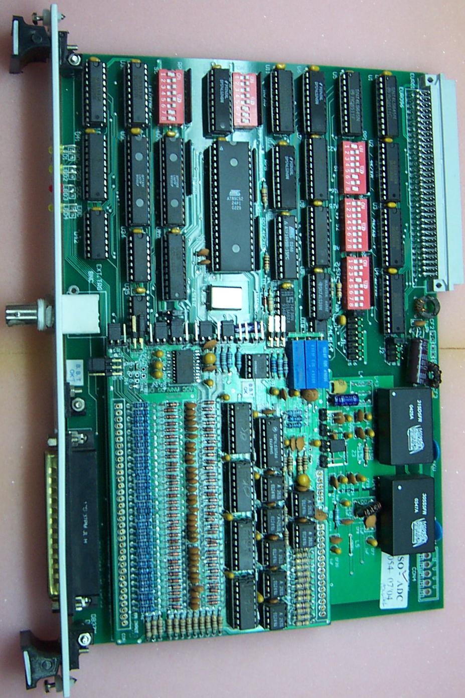
12 Bits ADC Board
- 16 differential/32 single ended analog inputs
- 12 bit resolution
- Free running mode of operation
- Look-up table for linearization of inputs
- Address selection through DIP switches
|
 |
| |
8 Channels DAC Board
- 8 analog unipolar outputs
- Voltage/Current outputs
- 16 bit resolution
- 4 channel opto-coupled outputs
- On-line output trimming facility
- Read back of set value
- Address selection through DIP switches
|
 |
| |
Digital Input Board
- 32 optically isolated inputs
- Input latching @ 8 MHz
- Channels can be configured to interrupt VME CPU
- Address selection through DIP switches
|
 |
| |
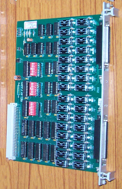
Relay Output Board
- 32 relay contact outputs, isolated & potential free
- Output status indication
- Address selection through DIP switches
|
 |
| |
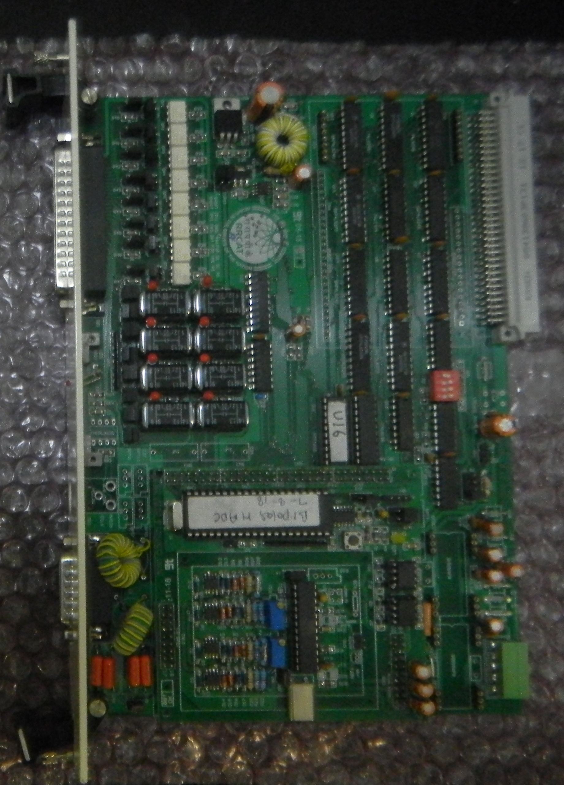
Bipolar DAC Board
- 8 Analog bipolar outputs
- 16 bit resolution
- Simultaneous update of all outputs
- On-board DC-DC Converter
- Address selection through DIP switches
|
 |
| |
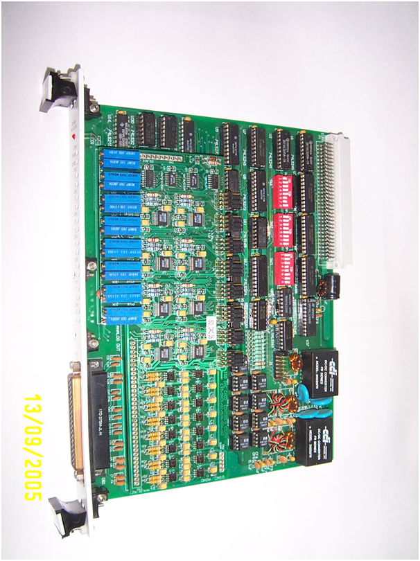
12 Bits Isolated ADC Board
- 16 channel Differential mode or 32 channel single ended analog inputs
- Onboard 1 K word FIFO
- Galvanic isolation between VME part and analog inputs
- Data Conversion rate 10 Ph sec
- Programmable modes of operations
- Board Address programmable by DIP switches
|
 |
| |
2 Channel 24 Bit ADC Board
- 2 Channel differential analog inputs
- Analog inputs galvanically isolated from VME
- Programmable data rate (10 Hz to 1000 Hz)
- Programmable operating and self calibration modes
- Board address programmable by DIP switches
- Optional oven for ADC & analog circuitry
- 64 K words on-board buffers
- 8 channel digital O/P (opto/relay isolated)
- 8 channel digital I/P (opto isolated)
- On board EPROM for Look Up Tables
|
 |
| |
16 Bit DAC Board
- Board Address selectable by DIP switches
- Isolation between output ground and VMEbus ground
- Selectable operation mode
- Optional function look-up table for function encoding
- Can be programmed to generate arbitrary waveform
- On board timers for setting the output with programmed time rate
|
 |
| |
4 Channel 16 Bit ADC Board-1
- Independent 4-analog input channels, each with its own 16-bit serial ADC
- Conversion time 10 usec
- Four digital input channels
- 24-bit address
- Start of conversion & VME interrupt on external trigger
- Selectable interrupt level (5/4/2/1) and Selectable 8-bit vector
- Selection of external orinternal SOC through jumper
- Second order filters at input with high input impedance and gain
- DC-to-DC converter for isolation between analog front-end and VME
- Xilinx CPLD 95108 for logic
|
|
| |
32 Channel Opto Input Board
- 32 Optically isolated inputs
- I/P latching @ 8 MHz
- Address selection through DIP switches
- CPLD based compare-and-interrupt logic
- Selectable Interrupt level and vector
- Scan and interrupt indication on front panel
|
|
| |
2 Channel 16 Bit ADC Board
- 2 Differential independent analog inputs
- Address selection through DIP switches
- Analog part isolated from VME
- Conversion on External Trigger
- VME-interrupter Module
- Optional function look-up table for function encoding
- 64 K words on-board buffers
- 8 Channel Digital I/P (Opto isolated)
- 8 Channel Digital O/P (Relay/Opto isolated)
|
|
| |
4 Channel 16 Bit ADC Board-2
- 4 channel single ended independent analog inputs
- 4 digital inputs
- Conversion on External Trigger
- VME-interrupter Module
- Analog part isolated from VME
- Address selection through DIP switches
- Selectable Interrupt level and vector
|
|
| |
|
|
|


