Development of Indigenous Helium Liquefier
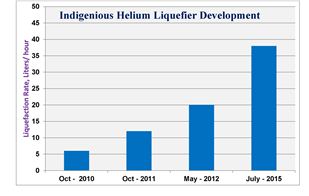
An indigenous helium liquefier based on reciprocating type expansion engine was developed during year 2010. Its liquafaction capacity is gradually increased from 6 lit/ hr to the present 35 lit/hr.
On August 14, 2010 at 21.15 hrs we achieved Helium liquefaction in fully indigenously designed and developed system for the first time. The system was further modified to liquefy and collect liquid helium in an external Dewar.
On October 13, 2010 we could collect liquid helium in an external Dewar. During its maiden trail itself, the system was operated for more than 25 hours continuously and more than 150 liters of liquid helium was collected in an external Dewar (Make CryoFab, Cap: 250 liters). The liquefaction rate achieved was about 6 lit/ hour.
On October 26, 2010. During second run the system was operated for more than 36 hours and more than 200 liters of liquid helium was collected in the external Dewar.
|
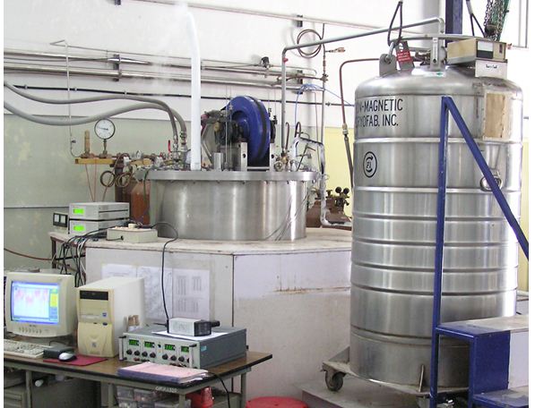
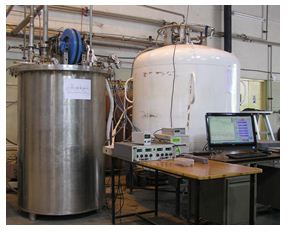
Photograph shows Helium Liquefaction system developed at RRCAT. It produced more than 150 Litres of Liquid helium in its first trail run |
Helium Liquefiers basically comprises of following components: expansion devices with work extraction mechanism, a train of efficient heat exchangers, pressure regulating devices etc.
Helium Liquefier system developed by us is based on two Reciprocating type expansion engines operating at 50K and 20K. These engines consist of extended length FRP pistons. FRP and long length results in reduction of heat in leaks form room temperature to the expansion space (Locally made FRP is used). Due to this length, the expansion process takes place deep inside the cold box, whereas other components of expansion engines such as fly wheel, inlet and exhaust valve actuators, work extraction mechanism (Brake), etc operates at room temperature. The gaps between the piston and liner, also called “void volume”, plays an important role in achieving the required expansion efficiency. Work extraction device used is alternator, used in automobiles, which is modified to suit the requirements. We have used six numbers of cross counter flow type heat exchangers operating between different temperature ranges.
High pressure helium gas finally cooled to about 7K or lower, with the combination of expansion engine and a train of heat exchangers, enters a Joule Thomson (J-T) expansion valve. On expansion through J-T valve, a fraction of the flow forms helium mist. This fraction depends on the temperature and pressure of helium gas at the beginning of J-T expansion (High Pressure) and the final expansion pressure. The J-T valve also, was designed and fabricated in house. Amount of this mist, to condense as liquid in the Dewar, strongly depends on the stability of pressure inside the Dewar. Achieving liquefaction for more than 36 hours continuously implies the stable pressure and temperature conditions maintained over the period. The other deciding factor for operation over long period is the handling of impurities in high pressure helium gas stream, especially oil carry over from main process compressor. An efficient oil removal system has to be employed for this purpose.
The oil removal system is also designed by us and fabricated by local fabricators. In addition to its design and fabrication, processing of components plays an important role in it. Locally available activated charcoal has been used in our system; its processing parameters were also established. Standard oil coalescing filters are used in this system.
The main process compressor, which maintains supply of pure oil free high pressure helium gas at about 230 psig and return low pressure of about 2 psig, is also procured from Indian manufacturer. It is an open type (belt driven), oil lubricated - air cooled - four stage - compressor supplied by M/s Sulzer, India, Model C4U217.4G. To handle the high heat of compression for helium gas, manufacturer has provided additional cooling. To avoid air in-leaks in the compressor during suction cycle, minor alterations were done in the process circuit of the compressor by us, after commissioning at RRCAT.
Gradually improvements were carried out to increase the liquefaction rate of this liquefier by adding liquid nitrogen pre-cooler stage and optimization of different parameters. With these changes the liquefaction rate of this liquefier touched 20 lit/hr. Due to limitation of present heat exchangers in handling higher gas flow and refrigeration produced by the expansion engines further enhancement in liquefaction rate was not possible in this system.
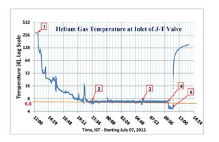
To further enhance the liquefaction rate, new reciprocating type cryogenic expansion engines with larger refrigeration capacity were designed and fabricated. Also, state of the art brazed alumium plate fin heat exchangers with high heat transfer rate and efficiency, coupled with low pressure drop were developed through a local vendor. Normally, in total six heat exchangers are required in a helium liquefier. First brazed aluminum plate fin heat exchanger built by the vendor for temperature range 300 to 80 K was integrated with the newly built reciprocating type expansion engines. Our current system uses brazed aluminum plate fin heat exchanger up to 80 K whereas below 80K finned tube in shell type heat exchangers from earlier system were integrated after suitably matching their thermal characteristics. One new compressor in parallel with the older compressor was integrated with the system to meet the required flow rate. With these modifications the liquefier was operated, its first cooldown performance is shown in Figure
Liquefier cooldown along with 250 litre main Dewar, both at room temperature, was started as shown by point (1). Cold box reached liquefaction temperature along with main Dewar as shown by point (2). Liquid started collecting in the Dewar, point (3). After about five hours of stable operation Dewar became full and liquid started flowing back through the return line. This brought down the J-T inlet temperature to 4.5 K, as shown by point (4). Helium plant was shut down at point (5). This system demonstrated a liquefaction capacity of more than 35 litre/hr. During subsequent trial runs the liquefier was integrated with one thousand litre helium Dewar.
This liquefier was operated with helium gas recovered form user experiments. For prolonged operation of this system with impure helium, an integral helium purifier design is in its advanced stage.
High efficiency brazed aluminium plate fin heat exchanger manufactured in India were first time successfully deployed in a helium liquefaction system. Six numbers of high efficiency brazed aluminum plate fin heat exchangers are being made to reach a liquefaction rate of 50 litre/ hr in the indigenous helium liquefier.
|