|
|
| Laser Materials Processing Division |
Failure Analysis of In-house Components
Failure Analysis of a High Voltage Feedthrough of Indus-2 Synchrotron Radiation Source
History of the component:
- The high voltage feedthrough (rated voltage: 10 kVDC) served in the beamline 17 (location: dipole magnet 7) of Indus-2 Synchrotron Radiation Source. The feedthrough was used to transmit power into the vacuum chamber.
- During operation, outside part of the feedthrough was exposed to ambient atmosphere and remaining part was exposed to vacuum (~ 10-9 mbar). The air side connector of the feedthrough was covered with a two-piece Teflon tube which is further covered inside an aluminium tube.
- Component was operated at room temperature and was exposed to at least two baking cycles (each involving heating to 150 - 200 °C for 24 hrs) during its entire operating life.
- Area around the failure site carried a number of polyurethane water tubes carrying cooling water for various components including magnets, photon absorbers etc. Several incidences of leakage of these water tubes are reported in the past. Relative humidity of the ambient atmosphere is usually in the range of 50 - 60%, although there was no online monitoring system for relative humidity.
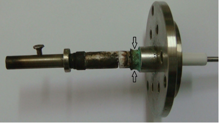
- Failure of high voltage feedthrough after 1 - 1.5 years of service (Fig.1).
Cause of failure:
- The main cause of the failure of the feedthrough was high humidity in the atmosphere surrounding the feedthrough assembly, which resulted in the corrosion of CuSil braze filler alloy at the ground terminal (arrow marked in Fig. 1) and also caused flashover between positive (+) and ground terminals.
- Thermal cycling of the insulator due to flashover resulted in spalling of glazed surface layer and assisted crack propagation from the flashover-generated surface defects.
Suggested remedial measures to avoid similar failures in future:
- Thorough cleaning of feedthrough and its connectors before installation,
- Use gasket-type sealing in the protective cover of the connector on the air side
- Use of metallic tubes in place of polyurethane cooling water tubes
- Design change of feedthrough to shift brazed joint to vacuum side.
|
| Fig.1: Failed feedthrough showing site of fracture and deposits formed on its outer surface. Arrow marked region shows corrosion of CuSil braze filler. |
Publication:R. K. Gupta et al., Practical Metallography, 58, 2021, 49-61.
|
|
|


