| FEL & Utilization Section |
 FEL & Utilization Section
Development of facilities for the utilization of Infra Red/Terahertz radiation from the IR-FEL and laboratory sources
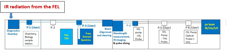
Figure 7 shows the layout of the complete experimental facility planned to be developed in near future in the user laboratories housed in the building adjacent to the IR-FEL tunnel, where experiments have been started using the IR-FEL radiation.
|
Figure 7: Layout of the IR-FEL user facility. The blue colour indicates the facilities already established. |
Experimental ports and facilities presently available for IR-FEL light based user experiments:
- Port P-1: Port ready with provision for delivering FEL light to the laser table installed. Actual setup to be installed by potential users as per their requirement for the planned experiments.
- Port P-3: IR-FEL light transmission studies in the frequency domain under low temperature (down to 5 K) and high magnetic field (up to 7 T) sample environment.
- Port P-4: Scanning and imaging of samples and absorption studies at room temperature using IR-FEL light
Complementary facilities for initial qualification of samples intended for study using the IR-FEL radiation:
- Frequency domain spectroscopy as a function of frequency (2 - 2000 cm-1 / 0.1- 50 THz / 3 mm- 5 microns), temperature (5 - 300 K) and magnetic field (up to 5 T).
THz Time Domain Spectroscopy as a function of temperature (2– 300 K) and magnetic field (up to 2 T) in the range 0.3– 3 THz or 10- 100 cm-1.
- Measurement of electrical resistivity, heat capacity, thermal conductivity, thermoelectric power and Hall effect as a function of temperature (2 - 400 K) and magnetic field (up to 8 T).
- Measurement of magnetization as a function of temperature (2 - 400 K) and magnetic field (up to 7 T)
Details of the existing and planned IR-FEL user facilities:
Six user ports have been planned for experiments using the IR-FEL light.
The port P-1 is identified for IR irradiation studies. It is ready for users to plan their experiments and to put up a commensurate user station.
|
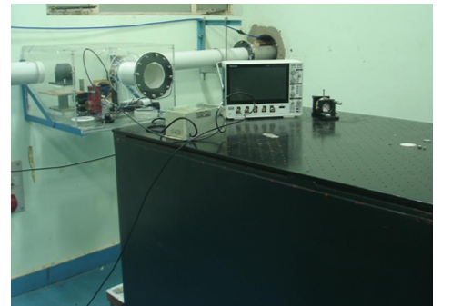
Figure 8: Port P-1 for FEL Physics studies and for setting up a facility for studies in Chemistry, Biology, and other areas. |
The port P-2 is kept free for future development.
The port P-3 has a facility for IR-FEL and laboratory source based studies in the frequency domain under low temperature and high magnetic field sample environment, and it is in regular use.
|
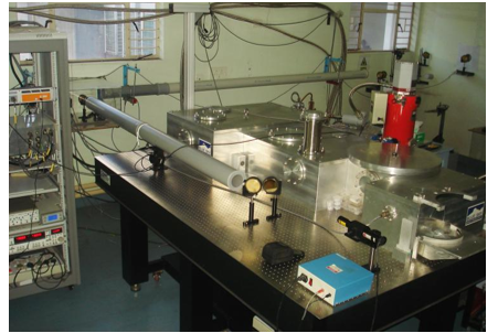
Figure 9: User Station for frequency domain spectroscopy: 300 K ≥ T ≥ 5 K, B ≤ 7 T |
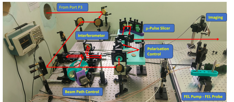
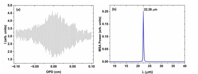
The port P-4 has a Michelson interferometer, which is used for IR-FEL wavelength measurement. Figure 10 shows this Michelson interferometer, along with adjacent components being developed for future, e.g., for IR-FEL light polarization control and pulse slicer for picking a single IR-FEL micropulse. An interferogram recorded in the Michelson interferometer using pyroelectric detectors is shown in figure 11(a). Figure 11(b) shows the near-single wavelength type spectrum of the IR-FEL light for a particular undulator gap. Such spectra are obtained from the interferograms after Fourier transformation. This measurement, which serves as the first step before doing any experiment with the IR-FEL light, takes about 10 minutes to perform, for a resolution of 5 cm-1. Presently, the best resolution achievable in this set-up is 0.2 cm-1.
|
Figure 10: Michelson interferometer developed at port P-4, along with facilities being developed for future including IR-FEL light polarization controller, pulse slicer, future IR-FEL pump - IR-FEL Probe experimental station. |
|
Figure 11: (b) A typical interferogram obtained in the Michelson interferometer for the measurement of IR-FEL wavelength. The interferrogram gives the light wavelength after Fourier transform as shown in (c). Here I = intensity, OPD = Zero path difference in between the arms of the Michelson interferrometer and MSA = mean square average. |
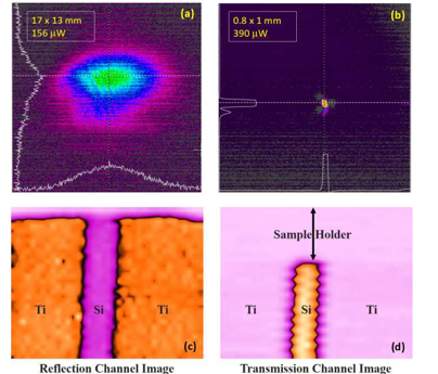
The port P-4 also has an experimental arrangement for scanning and imaging of samples. In this set-up, the IR-FEL light can be focused to a tight spot [figures 12(a) and (b)] and used for scanning-imaging with the help of pyroelectric detectors. The samples for imaging are mounted on a motorized precision xy-stage and rastered in front of focused IR light, and the images are collected in the transmitted and reflected channel simultaneously. Figures 12(c) and (d) show the images of a Ti-Si-Ti thin film device structure in the reflection and transmission modes respectively. The widows in the panels (c) and (d) represent 6 mm width approximately. A resolution of a few hundred microns is achieved in this set-up, which will soon be improved further by changing the objective lens.
|
Figure 12: Focusing the IR-FEL beam and scanning: (a) The original IR-FEL light spot, and (b) that obtained after focusing, both recorded in pyro-cam. Scanning-imaging of a Ti-Si-Ti thin film device structure in the (c) reflection and (d) transmission modes recorded using pyroelectric detectors. |
In the near future, the port P-4 will also have a picosecond laser based pulse picker facility with an IR-FEL pump - IR-FEL probe set-up. A 1064 nm picosecond laser system with provision for synchronizing with the clock frequency of the injector linac system of the IR-FEL has been installed in the user facility near the port P-6 (see figure 7) for use in the pulse picker for the IR-FEL based pump-probe facility. This will subsequently be replaced by a femtosecond laser system. The IR-FEL pump - IR-FEL probe facility is targeted to be set up by 2026.
The port P-5 will have an IR-FEL pump - THz probe experimental station at the port, with the same femtosecond laser system mentioned above employed to generate THz radiation. This experimental station is planned to be developed in 2028.
The port P-6 will have an an IR-FEL pump - optical probe experimental station, which can also be used for stand alone time domain spectroscopy using femtosecond laser pulses while the FEL radiation is being used at any of the other experimental stations. Discussions are underway with the UGC-DAE CSR, Indore Centre on the setting up of this facility. It is expected to be commissioned by 2026.
|
|
|
|