| Indus Synchrotron Radiation Facility
|
|
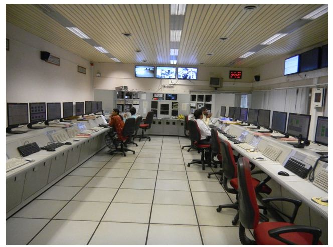
Fig. 1 shows a schematic of the Indus Accelerator Complex. The two sources, Indus-1 and Indus-2, share a common injector system consisting of a microtron and a booster synchrotron. The electrons are generated and accelerated to 20 MeV in the microtron and injected through a transfer line TL-1 into the booster synchrotron where its energy is increased to 450 MeV / 550 MeV. For injection into Indus-1, the 450 MeV electron beam is extracted from the synchrotron and then transported to the storage ring Indus-1 through the transfer line TL-2. This process of production, acceleration and injection is carried out every second till the current is accumulated to 100 mA in the Indus-1 storage ring. For the injection into Indus-2, a 550 MeV beam is extracted from the booster synchrotron and transported to Indus-2 through transfer lines, TL-2 and TL-3. Injection process continues till the beam current reaches a desired level. Subsequently beam energy is ramped to 2.5 GeV. Table.1 lists the main parameters of two synchrotron radiation sources: Indus-1 and Indus-2. Fig.2 depicts the Indus control room from where all the Indus accelerators are remotely operated.

|
Fig.1: A schematic of the Indus Accelerator Complex |
Table 1: Parameters of Indus-1 electron storage ring
Parameters |
Indus-1 |
Indus-2 |
Stored beam energy |
450 MeV |
2.5 GeV |
Beam current |
100 mA |
200 mA |
Circumference |
18.97 m |
172.47 m |
Beam energy (Injection) |
450 MeV |
550 MeV |
Critical wavelength |
61 Å |
1.98 Å |
Beam emittance( ξx, ξ y) |
7.0*10-8 m-rad
7.0*10-9 m-rad |
5.8*10-8 m-rad
5.8*10-10 m-rad |
Periodicity |
4 |
8 |
Dipole magnets |
4 |
16 |
Quadrupole magnets |
16 |
72 |
Sextupole magnets |
8 |
32 |
Harmonic number |
2 |
291 |
RF system frequency |
31.613 MHz |
505.812 MHz |
Energy loss per turn |
3.6 keV |
627 keV |
RF voltage |
22 kV |
1.27 MV |
|
Fig.2: A photograph of the Indus control room |
|
|