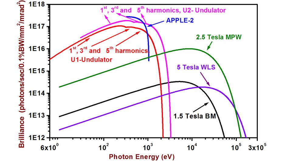
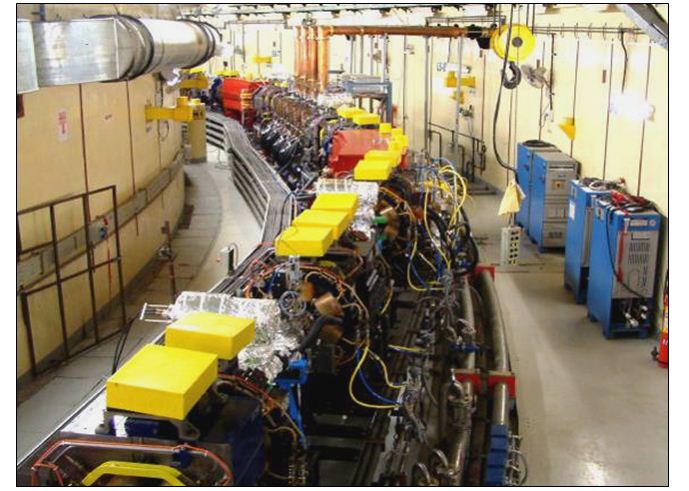
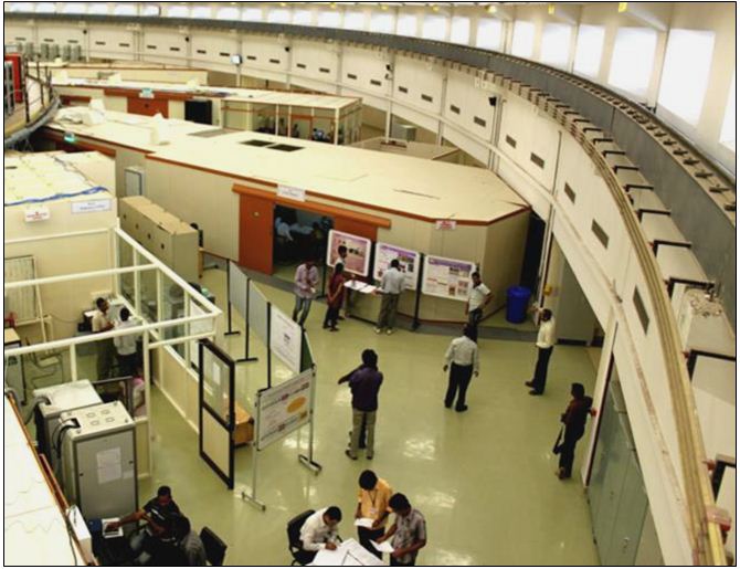
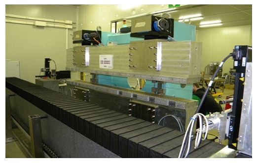
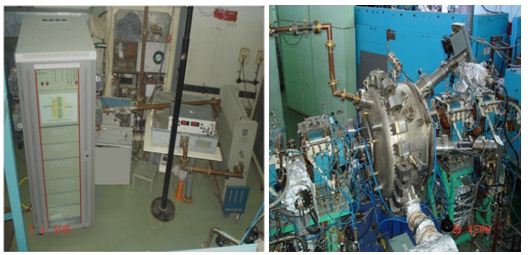
Fig.9 shows a section of the Indus-2 tunnel and fig.10 shows a section of the Indus-2 experimental hall. Various components of the accelerator such as magnets, power supplies, vacuum chambers and vacuum pumps, RF system, control system, timing system etc. are designed, developed and fabricated indigenously.
Control system
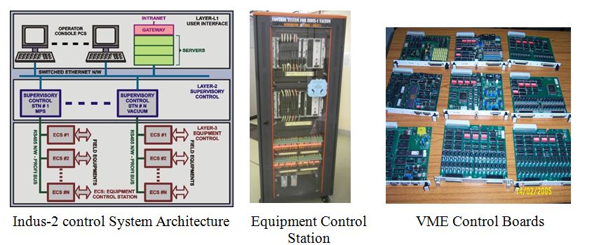
Indus control system facilitates remote operation of Indus accelerator facility. Present Indus control system comprises of two systems; one of them controls the microtron, synchrotron, Indus-1 and TL-1 and TL-2 and the other controls Indus-2 and TL-3. The former, an older system is based on peer to peer serial communication logic. It is being upgraded to a faster system using distributed architecture around faster multi-drop communications links and Ethernet. Indus-2 control system is a modern, highly functional and diverse system. It is divided into a number of intelligent sub-systems each of which autonomously controls a specific subsystem. Based on master slave architecture, the control system is distributed over three layers viz. User Interface (UI) layer, Supervisory Control (SC) layer and Equipment Control (EC) layer. The UI layer has operator consoles based on Windows PCs kept in the control room, while SC and EC layers are based on VME controllers running multitasking real time operating system. The UI layer is based on commercial SCADA system. Inter-layer communications are done using Ethernet and Profibus. All of the VME I/O cards are developed in-house.
Various functions performed with the control system include sub-systems start-up and shutdown, generation of stable and precise reference signals for various devices, providing precise triggers to facilitate beam injection, enabling different bunch filling patterns and energy ramping process, beam orbit and tune corrections, co ordination and handshaking with beam line front ends and operation of diagnostic beam lines. It also generates alarms in case of malfunctioning of a subsystem and operates safety interlocks to prevent damage to the facility and personnel.
The control system monitors about 400 critical interlock signals of various components and takes action automatically to safeguard the facility in case of potentially harmful conditions. The control system keeps watch on all machine parameters and raises alarms whenever abnormal conditions are detected. About 10,000 machine parameters are refreshed and logged every second in the central database. Logging of all operator interactions and system events helps in correlating the information that is crucial for trouble shooting in case of a system malfunction and helps in speedy recovery. Various diagnostics features and facilities are also provided to debug the unexpected events. Several web based tools are provided for convenient remote machine parameter and status monitoring and to manage day to day operations management functions. Fig.18 shows control system architecture, an equipment control station and various VME I/O boards.
|
Fig.18: Indus Control System |
Microwave system
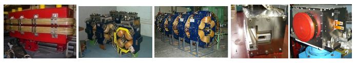
Electrons are accelerated in the microtron using a pillbox microwave cavity. The power to this cavity is supplied by means of a 2856 MHz pulsed microwave system powered by a 5 MW S-band klystron. The klystron needs about 200 W driver power which is provided by a 200 W solid state amplifier developed indigenously. The anode voltage of the 5 MW pulsed klystron is provided by means of a 130 kV line type pulse modulator designed and developed at RRCAT. The accelerating cavity and the waveguide transmission line were designed, fabricated and characterized in-house.
Ultrahigh vacuum systems
In order to reduce the scattering of electrons in Indus accelerators, ultrahigh vacuum (UHV) is created in the vacuum chambers through which electrons travel. In Indus-1 and Indus-2 storage rings, where the electrons are kept stored for several hours, the pressure is ~10
-9 mbar, whereas it is ~10
-8 mbar in the booster synchrotron where electrons stay for less than a second.
The Indus vacuum system is the largest UHV systems in India with a total length 323 m comprising of large number of vacuum pumps (~300) and gauges (~70). UHV is produced using sputter ion pumps (SIPs) and titanium sublimation pumps (TSPs). SIPs and TSPs used in Indus accelerators were developed indigenously. The pressure is measured using Penning gauges and Bayard Alpert gauges. The biggest challenge in achieving the UHV in such a big system is its conductance limitations due to small size of aperture of the vacuum chambers coupled with synchrotron radiation induced gas load.
The vacuum chambers of Indus-1, synchrotron and transfer lines are made of stainless steel. The vacuum chambers used in dipole and quadrupole magnets of synchrotron are of bellow type made of 0.3 mm thick stainless steel to avoid distortion of magnetic field generated due to eddy currents during magnetic field ramping. Handling high heat load of the order of 200 kW generated due to synchrotron radiation was a big challenge in Indus-2. The aluminium alloy 5083 H321 was chosen as the material of vacuum chambers in Indus 2 because of its high thermal conductivity. In addition, aluminium alloy has less Hydrogen and carbon dioxide than stainless steel and is nonmagnetic. The aluminium welding technology was developed for Indus-2 vacuum chambers. Photon absorbers made of OFHC were developed and installed in the dipole chambers to take care of the heat load of unused synchrotron radiation. The chambers are made with ante chambers to provide pumping ports and gauge ports. The aluminium alloy dipole vacuum chambers compatible for 10
-10 mbar.
Argon discharge cleaning, chemical cleaning and baking facilities have also been developed for conditioning of vacuum components before installation in the sources. Indus-2 vacuum system has been in operation uninterruptedly for the past 4 years with no need of opening the ring.
Beam diagnostics
Beam diagnostics plays a crucial role in the operation of an accelerator by providing information about the beam parameters required for smooth operation and optimization of the machine. Various beam parameters that need to be monitored are beam position, beam profile, beam current, betatron and synchrotron tunes, bunch length, coupled bunch modes etc.
In Indus accelerators, a number of beam diagnostic devices have been installed which are used during regular machine operation, machine experiments and studies. Beam profile monitors (BPMs) are used for visual observation of transverse shape, orientation and position of the beam in transfer lines and the storage rings. They use a fluorescent screen made of chromium-doped alumina, which can be inserted into the beam path and the spot generated by fluorescent light generated is viewed by a CCD.
Beam position indicators (BPIs) having four electrodes, are used to measure the position of the electron beam circulating in the accelerator vacuum chamber. The beam position data obtained from these BPIs is used to define and correct the beam orbit. In Indus-2, there are 56 BPIs uniformly distributed over the ring circumference. Using these BPIs, the beam orbit is corrected and kept stable within ±30µm using a slow orbit feedback system and a prototype local fast orbit system has been tested successfully to keep the beam orbit stable within ±3 µm. In addition, there are stripline monitors in Indus-2, which are used for measuring betatron tune, synchrotron tune and coupled bunch instabilities (CBM). The BPMs, BPIs and stripline monitors have been developed at RRCAT. Further, varioustypes of beam current monitors viz. DC Current Transformer (DCCT), Wall Current monitor (WCM) and Fast Current Transformer (FCT) have been installed in the Indus accelerators. The DCCTs are used to measure the average (stored) beam current in the rings and WCMs and FCTs are used to measure the bunch current in transfer lines and storage rings. WCMs and FCTs used in Indus accelerators have been developed at RRCAT.
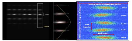
Two diagnostic beamlines namely X-ray Diagnostic Beamline (BL-24) and Visible Diagnostic Beamline (BL-23) have been designed, developed and commissioned on Indus-2. X-ray diagnostics beamline is primarily used for beam size and beam emittance measurement by using pinhole array based imaging. Visible diagnostic beamline is used for measurement of longitudinal parameters of the beam such as bunch length, bunch separation and bunch filling pattern. A dual sweep synchroscan streak camera is used for bunch length measurement with a resolution of ~ 5 ps. Typical images of pin-hole array and streak camera from X-ray and visible diagnostic beamline respectively are shown in fig.21.
|
Fig.21: Typical images of pin-hole array and streak camera from X-ray and visible diagnostic beamline respectively |
Survey and alignment of components
In a synchrotron, magnetic elements & diagnostic devices are aligned precisely to ensure circulation and storage of the electron beam. For example in Indus-2, quadrupole and dipole magnets are aligned within 0.1 mm accuracy about the design orbit and circumference has to be controlled within 2.5 mm, which is 15ppm of its circumference of 172.474m. This required a tight control over all the sources of errors associated with fabrication of components and involvement in defining the coordinates of Indus-2 building.
The procedure involved setting up a network of reference points, fixing of reference points on components to be aligned- in the form of conical base and targets, placement and precision alignment of components and overall survey to control the shape and size of the ring. To set up a network of reference points, the centre of the Indus-2 building was marked with respect to the booster synchrotron before commencing the construction of the building. All the survey control monuments and Indus-2 ring are constructed on the same rock. All magnets were fitted with required fiducials and level plates during their magnetic characterization on harmonic bench (for multipoles) using a laser and quadrant diode or on a CNC machine (for dipole magnets) with a Hall probe manipulator. Required alignment of components in the ring was achieved in various iterations. Full survey of Indus-2 involved measuring 1850 directions and 750 distances using the state of art instruments such as precision digital theodolites, invar wires, optical levels, and electronic inclinometers. A distance calibration facility equipped with a laser interferometer has been developed indigenously and is housed in an underground tunnel for temperature uniformity. An in-house developed software was used for survey data collection, least square adjustment, on-line coordinate measurements and error analysis. Periodic survey and alignment is carried out to maintain the magnets and other components in their required positions.
Coolant system
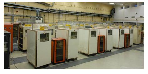
Accelerator cooling system provides low conductivity water (LCW) for cooling and maintaining at a fixed temperature various subsystems/components of Indus accelerators such as magnets, magnet power supplies, RF power sources and photon absorbers ensuring electrical isolation among them. There are two independent LCW plants � one for Indus-1 and the booster synchrotron and the other for Indus-2. Both the plants have been developed indigenously. Indus-2 plant has 4 MW cooling capacity and is in round the clock operation maintaining temperature at 30°C within ±. 1°C. It provides cooling water at 30°C within ±. 1°C with a electrical water conductivity less than 1µS/cm. In addition to the above centralized LCW plants, precision chillers are used for cooling RF cavities. The temperature stability requirements for Indus-2 cavities are most stringent. These cavities are maintained at a given temperature (25-75°C) with a stability of ±0.1°C. Four refrigerated air cooled systems each of 65 kW capacity have been developed for these cavities in collaboration with local industries.
Radiation safety
Radiation environment of the Indus synchrotron radiation facility comprising mainly of bremsstrahlung radiation having an energy spectrum extending up to the energy of electrons, produced as a result of the interaction of high energy electrons with structural materials of the accelerator or gas molecules within the vacuum chamber. In order to restrict the radiation level within the permissible levels in the experimental halls and other areas having human occupation, both the synchrotron radiation sources, Indus-1 & Indus-2 are housed in well shielded enclosures. Indus-1 is housed in a hybrid shield enclosure made of mild steel (8 cm) and lead (8 cm). As mentioned earlier, Indus-2 is housed in a well shielded tunnel with an outer shielding of 1.5 m thick ordinary concrete and inner shielding of 0.6 m. Entry to the accelerator area is prohibited during operation of the accelerators. Beamlines in Indus-2 are housed in specially designed shielded hutches and experiments are performed in experimental hutches, which are also shielded. In these beamlines, apart from bremsstrahlung and photo-neutrons, synchrotron radiation is the major contributor to the dose rate in the experimental hutches.
Various radiation safety systems like door interlocks, search & secure systems, kori-locks, audio-visual warnings etc. are provided to prevent any accidental trapping and subsequent radiation exposure to working personnel or users in the facility. Online radiation monitoring is done with the help of installed area radiation monitoring system, comprising of ion chambers and moderated BF3 counter based neutron detectors. Regular radiation surveys are also performed by trained and qualified health physicists and radiation workers are provided with personnel monitoring devices. Indus safety review committee reviews the safety status periodically and final review is performed by regulatory committee constituted by AERB and the recommendations are complied with.
Orbit Feedback Systems in Indus-2:
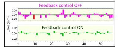
1. Global Slow Orbit Feedback System (SOFB): The orbit of the stored beam is required to be corrected and kept stable so that the photon beam of specified intensity is available at the experimental stations in the beamlines. For orbit correction, 56 beam position indicators (BPIs) are used to acquire the beam positions and this information is used to correct the beam orbit using 48 horizontal and 40 vertical correctors. The beam orbit in Indus-2 is corrected as per the user requirement and kept stable within ±30µm using a global SOFB system operating at repetition rate 0.05 Hz as shown in fig.22. For further orbit stabilization, orbit movement due to fast perturbations needs to be globally corrected.
|
Fig.22: Result of slow orbit feedback system (Vertical scales in the two figures are different by a factor of 10) |
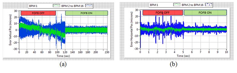
2. Global Fast Orbit Feedback System (FOFB): To increase electron beam orbit stability above the level achieved by global SOFB system, the global Fast Orbit feedback system has been developed in its initial phase with 16 BPIs and 32 correctors, integrated and tested in Indus-2 storage ring. This helped attenuating orbit changes starting from nearly DC upto 50Hz in both horizontal as well as vertical plane. The system has been tested in which the position data at ~10 kHz rate obtained from BPIs equipped with digital processing electronics have been used. The developed system successfully confined the beam position variations (pk-pk) from ~ ±40µm to ~ ±12µm in horizontal plane and from ~ ±30µm to ~ ±10µm in vertical plane (Fig.23). In this first phase development, noise attenuation of ~5dB at 50Hz has been achieved in both the planes.
|
Fig.23: Measured beam position on different BPIs with Global FOFB system OFF and ON (a) horizontal Plane (b) vertical plane |
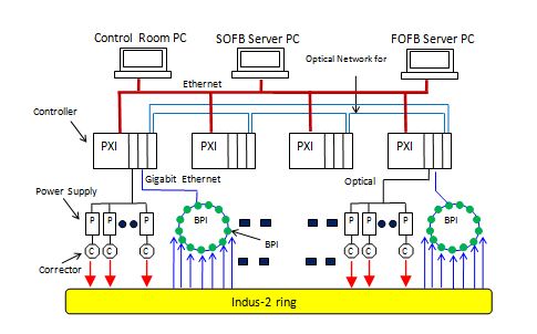
Fig.24 shows a schematic of the global fast orbit feedback system implementation.
|
Fig.24: Global Fast Orbit Feedback System (FOFB) for Indus-2 |
Tune Feedback System
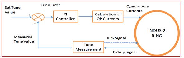
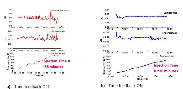
Betatron tune plays a crucial role in the performance of a synchrotron light source.In a synchrotron or storage ring, betatron tunes need to remain constant during machine operation which otherwise may drift and cause beam loss via resonance process. Variation in betatron tune value may occur due to the reasons such as closed orbit perturbations and misalignment of sextupole magnet, interaction of electrons and residual gas molecules, current dependent phenomena, fluctuation in quadrupole power supply etc. In Indus-2, a tune feedback system has been implemented. A schematic block diagram of the system is shown in figure 1. Betatron tunes are measured by a tune measurement system by applying a transverse excitation to the beam using a swept frequency CW RF source. The measured tune values are updated online at every 5 sec interval. To control the betatron tune, tune measurement system and quadrupole magnet current control system are interfaced with the tune control software. The tune is corrected in both horizontal (H) and vertical (V) planes via two groups of quadrupoles among five groups of quadrupoles. The tune error signal is applied to a PI control logic which gives the required change in quadrupole to correct the tune. The PI coefficients are optimized to make the system stable and fast converging. The system bandwidth is 0.05 Hz and the residual variation in fractional tune is ±0.0005.
|
Fig.25: Schematic diagram of tune feedback system |
| |
|
Fig.26: Typical tune variation graph with and without tune feedback system |
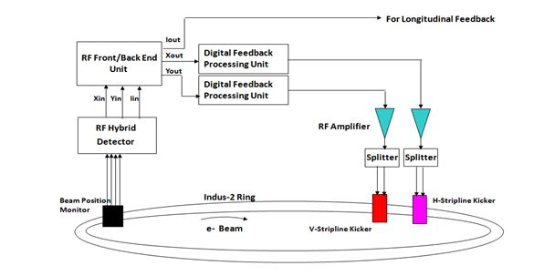
Transverse bunch by bunch feedback system
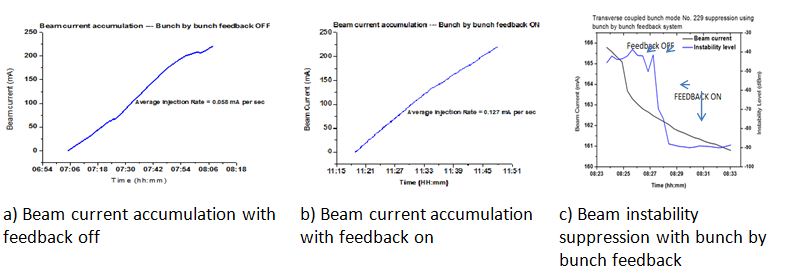
In a storage ring, at high beam currents, transverse instability of the beam adversely affects the machine performance like saturation in beam accumulation, partial or complete beam loss during the beam energy ramping and increase in the transverse beam size. These instabilities can be controlled by the transverse bunch-by-bunch feedback system. In Indus-2, a transverse bunch by bunch feedback system has been implemented. Schematic block diagram of the system is shown in figure 27. The main components of the feedback system are: beam position monitor, RF hybrid detector for real-time beam position and intensity signal detection, RF front/back-end unit, digital feedback processing units, power splitter, phase shifter unit, RF amplifiers and stripline kickers which are used to apply the correcting kick. The feedback system parameters have been optimized for operation at beam injection energy of 550 MeV, beam energy ramping and stored beam at 2.5 GeV. This system also helps in achieving beam current above 200 mA at beam injection by reducing the beam oscillation due to injection kicker. It is observed that it helps to reduce the beam injection time by a factor of ~1.3-1.5 times. Typical results are shown in fig.28.
|
Fig.27: Schematic block diagram of transverse bunch by bunch feedback system |
| |
|
Fig.28: Typical graphs showing beam injection rate improvement and instability suppression with bunch by bunch feedback system |
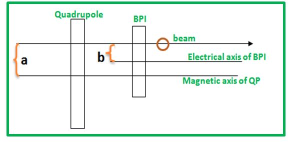
Beam Based Alignment (BBA)
The offset between Beam position Indicator(BPI) and its adjacent quadrupole (QP) magnet is determined using technique of BBA.
|
Fig.29: Working of Beam Based Alignment |
Alignment of quadrupoles in accelerator is a prerequisite to achieve the optimum performance. The conventional mechanical alignment couldn�t serve the purpose alone. Hence BBA is required in which beam is used as an alignment tool (fig.29).
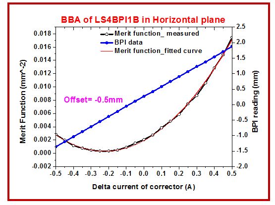
With beam based alignment one can reduce Closed orbit distortion (COD) further, the strength of corrector magnet used in COD correction are also minimized and will also result in increment of beam lifetime due to increased aperture. Using BBA, the offset of ~ -1 mm in vertical and ~ 0.5 mm in horizontal plane in one BPI viz LS4BPI1B of Indus-2 has been found(fig.30). In future the offset of all 56 BPIs will be determined after connecting all 72 quadrupoles with individual shunt power supplies.
|
Fig.30:Results of BBA of LS4BPI1B in horizontal plane |