 Home Accelerator Power Supplies Division
Transformer Facility
Home Accelerator Power Supplies Division
Transformer Facility
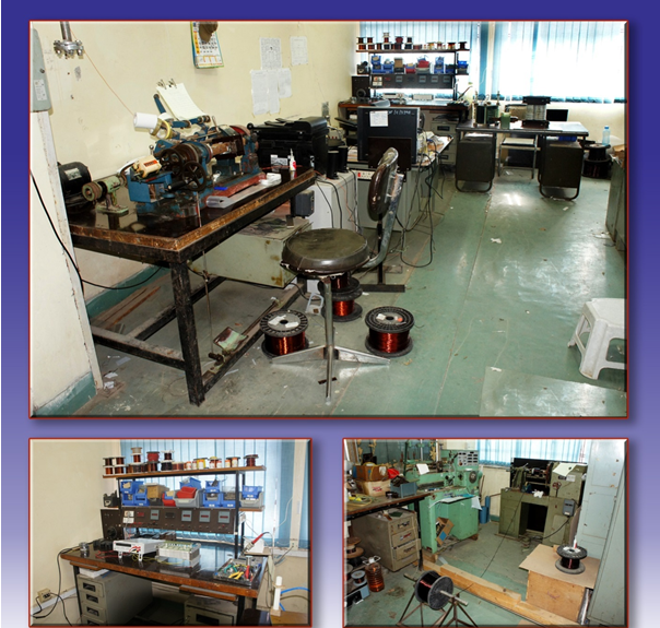
With a view to making lightweight, high-frequency transformers or low-frequency transformers and inductors required for various power supplies developed here and to obviate the delay in procurement of the non-standard and special types of transformers, an in-house transformer facility has been started initially at RRCAT with a little infrastructure. Gradually, after taking the factors like quality, economy and special requirement into consideration, the aforementioned facility has been expanded over the course of time by adding relevant machinery.
|
Transformer Fabrication Facility |
Major Activities
These include, inter alia, design, production, repair and development of transformers using different core materials, construction methods, winding techniques, cooling methods and insulating materials and performance improvement with the available resources.
Specifications of some of the transformers and inductors fabricated
1-Φ 2 kVA 50 Hz 230V/20 kV transformer, 1-Φ 40 kHz 30 kVA 400V/44kV oil- cooled transformer, 1-Φ 40kHz 60 kV/30V 15A transformer, 93 mH 3Amp 60 kV 40.7 kHz inductors, 1-Φ 25 kHz 7.5 kVA 200V / 10,000 V shell type transformer etc.
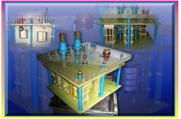
Magnetic components pertinent to high voltage generator of 750 keV DC accelerator
High frequency transformers and inductors required in 750 keV DC Accelerator required for R&D in the field of radiation processing have been designed and made. Specifications include 1-Φ 40 kHz 30 kVA 400 V / 44 kV transformer, 48-0-48 mH, 45-0-45 kV, 40 kHz compensating inductors, etc.
|
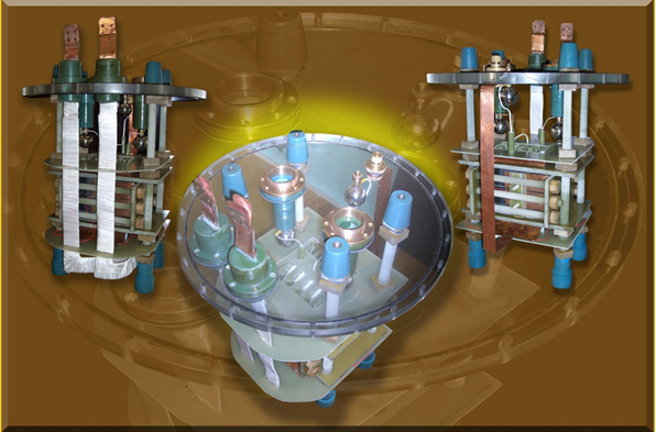
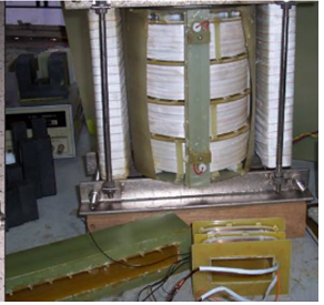
Fig: 1-Φ 40 kHz 400V: 45kV-0-45 kV Ferrite cored shell type Transformer |
For 400V: 45kV-0-45 kV/ 40 kHz HV transformer, two transformers of 400V : 32 kV, 40 kHz are used in a centre-tap configuration and 5 transformer of 400V : 6.4 kV, 40 kHz are used to realize one single unit. U-I ferrite cores have been used in these transformers.
|
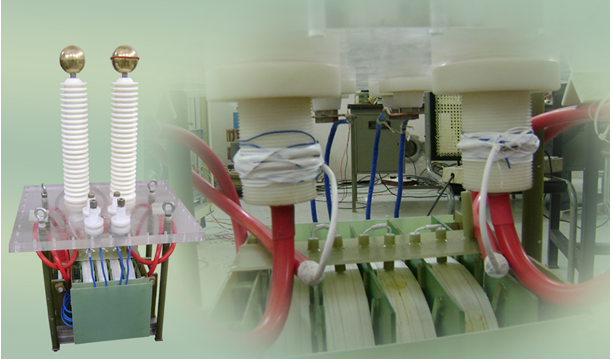
1-Φ 40 kHz 30 kVA 400 V / 44 kV Transformer |
|
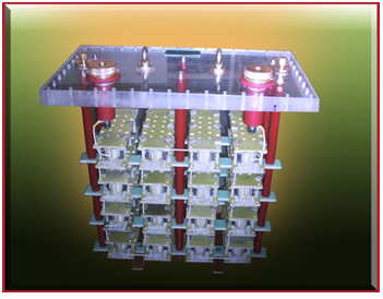
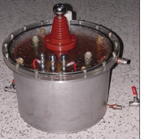
Here, 16 inductors of 6 mH, and 4.5 kV are assembled in a single tank to realize a 48-0-48 mH, 45-0-45 kV, 40 kHz compensating inductors in which E type Ferrite cores have been used. |
45 kV, 40 kHz compensating Inductor |
In high voltage power supplies for dc accelerators, the size and weight of the system are critical. Hence greater attention is required to curb the overall size and weight of the transformers along with other components. These are met by operating the transformers at high frequency. Besides, these transformers have a significant influence on the overall performance and efficiency of the system. Various parameters taken into consideration while designing the transformers for the afore-stated applications include, inter alia, output power delivered to the system within specified regulation limits, maximum power loss that can be allowed, maximum temperature rise, volume occupied, and minimization of weight and cost. Depending on the application, some of these parameters dominate.
|
|
1-Φ 15 kVA, 40 kHz, 400V/22kV ferrite-cored oil-cooled transformer |
1-Φ 2 kVA, 50 Hz, 230V/20kV transformer |
Transformers for different power supplies
Pulse transformers pertinent to H.V. pulse charging power supply that has been developed by team of Pulsed Power Supp. Lab and a -50 kV electron gun high voltage pulse power supply have been made. Team of this lab is also involved in the development and fabrication of the magnetic components of the active shunt P/s and Fast Orbit Feedback System, I-2 Refurbished power supply, DC power supply for Indus-1 2π monitor, active filter, solid state pulser, etc.
|
500 µsec 3 kV / 75 kV Oil cooled pulse Transformer |
|
1-Φ 25 kHz 7.5 kVA 200V / 10,000 V shell type Transformer |
Other transformer related activities
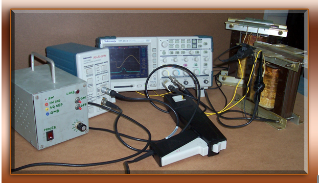
Investigation of the effect of winding geometry on inrush current
|
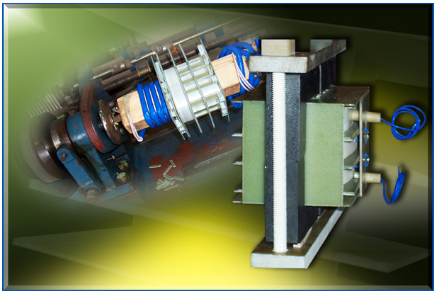
Experimental set up for investigating the effect of winding geometry on inrush current |
Since the inrush current might be seriously disturbing phenomenon, it behoves us to give heed to the same and investigate the effect of winding geometry and its placement on the inrush current of a single-phase transformer. Apropos of this, differently from traditional methods, a few types of practical methods have been dwelled upon to enfeeble the inrush phenomenon and abate inrush currents.
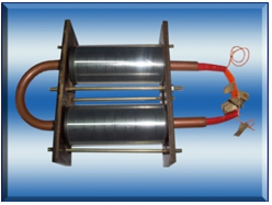
Coaxially wound transformer
|
Here, with a view to having robust transformers and transformers in which leakage inductance is easily controllable, work on single-phase coaxially wound transformer has been taken up. |
Fig: Coaxially wound transformer |
Studies pertinent to surge protection methods and their impact on transformer parameters
|
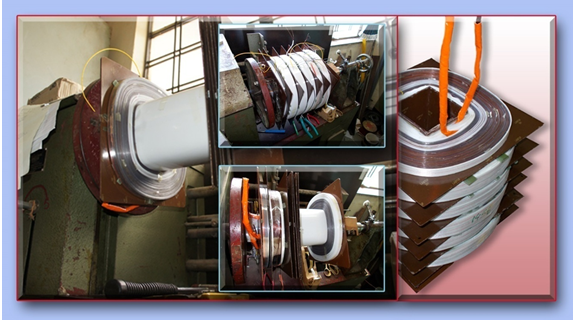
Fabrication of Transformer coils with reinforced end turns |
Considering the effect of voltage surges reaching the transformer terminals and importance of surge protection, the study of impact of measures taken to take care of non-uniform surge voltage distribution on high voltage transformer parameters has been embarked upon.