| Accelerator Power Supplies Division |
 Home Accelerator Power Supplies Division
Pulsed Power Supply Section
Home Accelerator Power Supplies Division
Pulsed Power Supply Section
- Mandate
-
Team Members
- Activities pursued in Pulsed Power Supply Section
-
Other Development works
- Publication
- Invited Talks
1. Mandate
Pulsed Power Supply Section is involved in design and development precision pulse power sources for Indus Accelerators. Fast pulse magnetic fields are required to facilitate injection and extraction of particle beams from transport lines to rings and vice-versa. These sources are used to energise pulse magnets in the machine to produce fast pulse magnetic fields. These power sources are known for their stringent performance requirement in terms of high amplitude stability, low jitter, repeatability and pulse shape.
Pulsers producing various types of pulse shapes viz. half sine, sine rise to peak followed by fast exponential fall and trapezoidal pulses have been developed and working in round the clock operation of machine. In the process of development of these pulse power sources, the team working in PPSS has gained expertise in precision Pulse Forming Network chargers, design of pulse power circuits for various pulse shapes and their high voltage discharge circuits. The team has gained expertise in high voltage, high di/dt, high current switching, a typical characteristic of these pulsers.
In addition to this, PPSS has worked and is pursuing high voltage, high current semiconductor switches, high stability (100 ppm) capacitor chargers, high performance high power ac - dc converters for dynamic loads and active filters. Active filters has been developed for harmonic correction of a.c line currents as well as D.C. side ripple correction of high power rectifiers.
2. Team Members
Present team members are as follows:
- Yash Pal Singh
- Yogesh Kelkar
- U.S. Karandikar
- Rajesh Barothiya
- Lingam Srinivas
- Yogesh Raikwar
- Amresh Chandra Pandey
- Satya Dav
- Yunus Khan
- Raju
3. Activities pursued in Pulsed Power Supply Section
- Pulsed Magnet Power Supplies for Indus-1
- Pulsed Magnet Power Supplies for Indus-2
Pulsed Magnet Power Supplies for Indus-1
The specifications of pulse power supplies required for booster (injection and extraction) and the Indus-1 SRS (injection) are listed in following table-
| Parameters
|
Booster Injection Kicker
|
Booster Injection Septum
|
Booster Extraction Kicker
|
Booster Extraction
Septum
|
Indus-1 Injection
Septum
|
Indus-1 SRS Injection Kicker
|
| Peak current | 1000 A | 5000 A | 2400 A | 6000 A | 6000 A | 5000 A |
| Pulse width | 13 μs | 200 μs | 0.1 μs | 200 μs | 200 μs | 1.2 μs (Rise) and fall time constant of 120 ns |
| Pulse Shape | Half Sine | Half Sine | Trapezoidal | Half Sine | Half Sine |
| Jitter | < 50 ns | < 50 ns | < 10 ns | < 50 ns | < 50 ns | < 10ns |
| Load Inductance | 0.46 μH | 1.02 μH | 0.6 μH | 1.76 μH | 1.76 μH | 0.6 μH |
The pulsed magnet power supplies have been developed to cater different pulse shapes requirements namely half sinusoidal, trapezoidal and damped sinusoidal rise and exponential fall. A brief description about the pulsers on the basis of pulse shapes is as follows-
Pulse Shape - Half Sinusoidal
The booster injection kickers, booster injection septum, booster extraction septum and Indus 1 injection septum magnets are energized by a pulse current of half sinusoidal shape. The pulse width varies in the range 13 micro seconds to 200 micro seconds and the peak current varies from 700 A to 5 kA for different magnets. These pulses are generated by discharging a bank of energy storage capacitors into the inductive load of septum magnet via a thyristor switch to form an under damped LCR circuit. Capacitor charging scheme for repeated charging of capacitor bank has been designed to deliver high degree of repeatability and stability for voltage of capacitor bank.
|
|
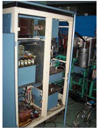
Booster injection septum |
Booster extraction septum |
Pulse Shape - Trapezoidal
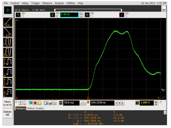
The booster extraction kicker magnet is energized by a pulse current of trapezoidal shape. The rise time of current pulse is 50 ns and the flat-top time is typically 70 ns. Coaxial cable of high voltage has been used as a pulse forming network. This cable is charged to a requisite voltage and discharged into the load by a Thyratron switch. A matched resistance of cable characteristic impedance has been used in series with load magnet.
|
|
Booster extraction kicker |
Thyratron assembly |
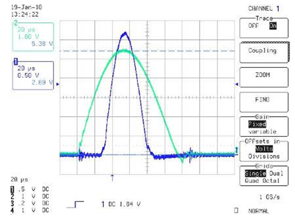
|
Booster extraction kicker current pulse |
Pulse Shape - Damped Sinusoidal Rise and Exponential Fall
The Indus-1 SRS injection kicker magnet is energized by a pulse current characterized by damped sinusoidal rise to peak and exponential fall from current peak. The rise time is 1.2 μs and fall time constant is 120 ns.
|
Indus-1 SRS injection kicker |
Pulsed Magnet Power Supplies for Indus-2
Output current waveform, for all the pulsed magnet power supplies for Indus-2 pulse magnets, is half sinusoidal.
- Indus-2 Septum Magnet Power Supplies
- Indus-2 Kicker Magnet Power Supplies
The specifications of pulse magnet power supplies required for Indus-2 are listed in the following table-
| Parameters |
Thin Spetum |
Thick Septum |
Injection Kicker |
| Beam energy (MeV) | 700 | 700 | 700 |
| Angle(o) | 2 and 3.6 | 19 | 1.4 |
| Peak current (A) | 5300 | 8500 | 11000 |
| Charging voltage (V) | 750 | 1000 | 28000 |
| Inductance (μH) | 0.95 | 2.7 | 0.84 |
| Pulse shape | Half sine wave | Half sine wave | Half sine wave |
| Pulse duration (μs) | 50 | 100 | 3 |
| Repetition rate (Hz) | 1 | 1 | 1 |
| Amplitude stability | 1 x 10⁻⁴ | 1 x 10⁻⁴ | 1 x 10⁻³ |
| Jitter (ns) | 100 | 100 | 10 |
Indus-2 Septum Magnet Power Supplies
The Indus-2 septum magnets (thin and thick) require half sine wave current pulse. These pulses are generated by discharging a bank of energy storage capacitors into the inductive load of septum magnet via a thyristor switch to form an under damped LCR circuit. The injection of bunches takes place at the peak (flat top) of the half sine wave. A bank of energy storage capacitors has been realized such that the series inductance of the circuit remains low. Eight RG-8/U cables form flexible connection link between power supply and magnet. The whole arrangement was made coaxial to reduce stray inductance.
|
|
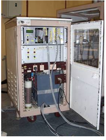
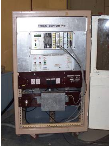
Indus-2 thin septum |
Indus-2 thick septum |
|
Current waveform of thick and thin septum |
Indus-2 Kicker Power Supplies
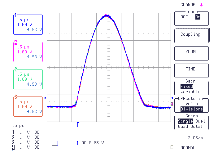
In Indus-2 injection will be carried out by using horizontal multi-turn injection scheme. In this scheme a compensated orbit bump is produced and an electron beam is injected parallel to the bumped orbit via septum magnet. Injection will be carried out in the first long straight section, LS-1. The compensated bump will be produced by using four kicker magnets. A half sine wave type of current pulse has been fixed for Indus-2 kicker power supplies. Injection will take place around peak value of sinusoidal current. Base width of half sine current has been decided to be 3μs. Current peak required to give requisite deflection has been fixed to be 11 kA.
|
|
Injection kicker power supply |
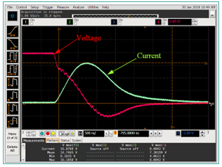
The required features for the kicker magnet power supplies are: 1) All the four kicker current pulses should have identical waveforms, 2) Kicker current pulse should have requisite degree of pulse to pulse current stability around peak, 3) Kicker current should reduce to a very low value in 1.5μs to 1.6μs from peak so as to reduce the compensated bump to zero, 4) Kicker current pulse should not go negative as it will disturb the stored beam. All the four kickers have identical mechanical arrangements for pulse generating elements. The peak of the current pulse is stabilized by keeping final stage capacitor voltage constant at a required value. Discharge switch, operating at 1Hz, has to pass a peak current of 11kA at a maximum di/dt of approximately 15 kA/μs which is reduced then by employing a magnetic assist. Time jitter requirement of the pulse is 10 nsec.
|
|
Matched Current waveforms of all kickers |
4. Other Development works
With a view to create upgrades on existing systems in terms of performance, specifications and use of newer and advanced technologies, Pulsed Power Supply Section is continuously working in R&D of pulse systems to create superior solutions to our present and future needs. Some of these developments are listed below.
Development of solid state switch based Pulsers
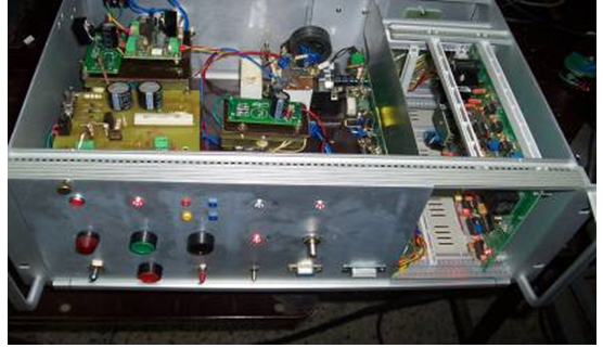
A series connected high voltage IGBT switch has been developed for pulsed power application using conventionally available devices of rating 1700V, 26A. Static and dynamic voltage sharing networks are used along with active clamp method for protection of series connected IGBT’s. The gate drives are provided using fiber-optic cables which gives necessary galvanic isolation. The developed switch has a capability of switching 8 kV voltage and generating 1.6kA current with 3.5us pulse width at a PRR of 1 Hz. This development will lead to replacement of costly imported Thyratron switches upto certain voltage/current ratings using economical and commercially available devices.
|
Pulse power circuit along with IGBT driver stack |
|
1.6 kA peak current using series switches |
Modified Booster Injection Kickers for Booster up-gradation
Modified Booster Injection Kickers has been developed to deliver a pulse with 5 microsecond sinusoidal rise and 700 ns linear fall at 700A peak current for up-gradation of booster. Power supply uses a very compact pulse power circuit to meet stringent requirement of linear fall of current with high di/dt .
Line side Active Filter
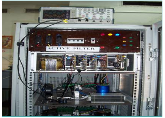
A 3 Phase line side active filter has been designed and developed in lab. This filter, when connected at the power supply end of a three phase non linear load, will supply the harmonic currents drawn by the load locally. Thus currents drawn from the a.c. mains remain nearly sinusoidal thereby reducing harmonic distortion on power lines. A three phase line side harmonic filter has been designed, developed and tested on a 400V, 3 phase, 50 Hz, 7.5 kVA well filtered diode bridge rectifier load to compensate the harmonic currents drawn by the rectifier.
|
Active filter for line current harmonic correction |
25 Hz PRR capacitor charging power supply with twin phase shifted primary windings to achieve high charge transfer rate and high stability
A capacitor charging power supply (CCPS) was developed to charge bank of 50uF energy storage capacitor upto 2.5 kV in 35ms exhibiting a peak charging power of 4464 J/s at a repetition rate of 25pps. The High Voltage capacitor charging power supply consist of two identical full bridge resonant converters feeding to two primary windings of a transformer with rectified secondary connected to capacitor load. Topology selection is based on the fact that the series resonant converter with switching frequency f s, below 50% of the resonant frequency f r (f s <= 0.5 f r) act as a current source. Three phase controlled DC bus, twin phase shifted primary winding fed resonant converter and voltage comparator loop will ensure ± 100 ppm peak current stability.
|
|
Output transformer and IGBT drivers |
Power supply front panel |
Phase-Shift PWM Based Capacitor Charging Power Supply
A high voltage power supply has been developed for constant average current capacitor charging. PWM based charger has reduced peak current hence lowered losses. Phase-Shifted PWM has achieved soft switching without extra components. Constant average current capacitor charging has been achieved with a sensorless novel control scheme . A double two-switch bridge has enhanced reliability. Power supply has been developed to charge a capacitor of 50uF to 2.5 kV at a pulse repetition rate of 25Hz.
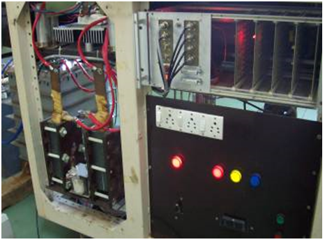
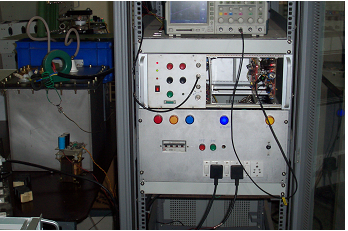
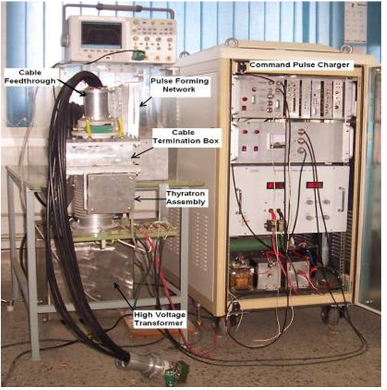
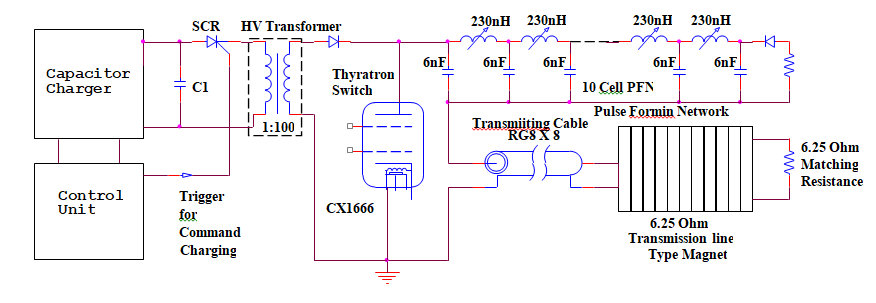
Pulse Power Supply For Transmission Line Type Kicker Magnet
A 25 Hz kicker power supply has been designed and developed to test a 6.25 ohm transmission line type kicker magnet for technological development for perceived future needs. This power supply delivers a 2kA trapezoidal current pulse with a rise, fall and flat top time of 100ns, 100ns and 500ns respectively. The current pulse is generated by discharging a pulse forming network into matched transmission line kicker magnet. A high voltage thyratron CX1666 is used as a switch. The design of PFN was a critical issue from the fabrication point of view due to smaller impedance and faster rise time requirement. We have dealt with the specific issues related to the pulse charger, design of pulse forming network and thyratron assembly for achieving faster rise time of current pulse.
|
|
Developed high voltage pulse power supply and its schematic |
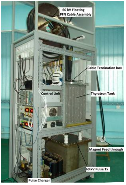
A 60kV high voltage pulse power supply has been designed and developed to test a 12.5 Ω transmission line type kicker magnet for technological development for perceived future needs. This power supply delivers a 2kA trapezoidal current pulse with a rise, fall and flat top time of 70ns, 100ns and 70ns respectively. The current pulse is generated by discharging a charged pulse forming network into matched load. A high voltage thyratron CX1836 is used as a switch. The design of PFN, low inductance thyratron assembly and termination box at 50 kV were few critical issues for faster rise time requirement. We have dealt with the specific issues related to the pulse charger, design of pulse forming network and thyratron assembly for achieving faster rise time of current pulse.
|
60kV pulse power supply for fast rise current pulses |
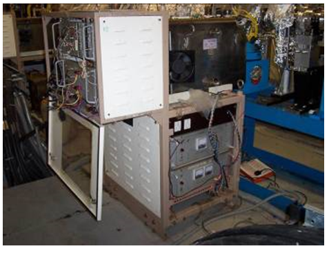
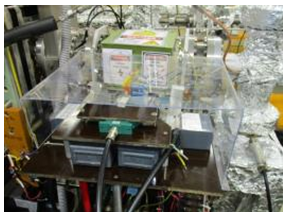
Pinger Magnet Power Supply Development Work
A pinger magnet system will consist of two types of magnets namely Horizontal and Vertical pinger magnet. These pinger (kicker) magnets are energized by two separate power supplies. These magnets will generate betatron oscillation in the stored beam of Indus 2. These magnets will act as a tool to probe the linear and non linear dynamics of the beam. The turn by turn oscillations is captured by BPMs of the ring. A vertical pinger power supply was commissioned in Indus -2 to deliver 5700 Amps of peak current at 1 Hz PRR. The photograph of the developed power supply and current waveform is attached below.
|
|
Developed power supply |
PFN assembly |
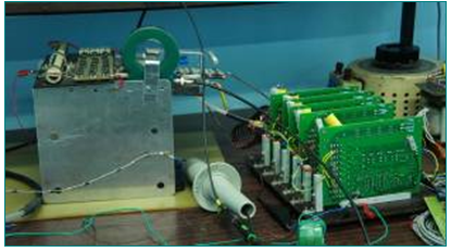
A horizontal pinger power was installed and commissioned in Indus-2 to deliver 2700 Amps of peak current at 1 Hz PRR. The photograph of the developed power supply is attached below.
|
|
Developed power supply |
PFN assembly |
5. List of Publications:
- Y.kelkar, R. Barothiya,U. Karandikar, Y.P. Singh, A.C. Thakurta and S. Kotaiah,
” High Stability Septum Magnet Power Supply For Indus-2”,
InPAC 2003, Page no 410
- Y.P. Singh, U. Karandikar , R. Barothiya, Y.kelkar, A.C. Thakurta and S. Kotaiah ,
”Development of Indus-2 Kicker Power Supplies”,
InPAC 2003, Page no 416
- U. Karandikar , Y.P. Singh, R. Barothiya, Y.kelkar, A.C. Thakurta and S. Kotaiah,
”Upgradation of Extraction Kicker Magnet Power Supply of Booster for Indus-2- Present Status”,
InPAC 2003
- R. Barothiya, Puntambekar T.A.,
“Trigger delay drift correction system for pulsed power supply of Indus-II",
InPAC-2005 at VECC, Kolkata
- M. L. Gandhi, A.C. Thakurta, Ulhas Karandikar,
“Mitigation of Stability Problems of Pulsers for Injection Kicker Magnet of Indus-II”
Indian Particle Accelerator Conference - 2005 (InPAC-05)
- Y.Kelkar,U.S.Karandikar,R.Barothiya,Y.Singh,A.C.Thakurta,S.Kotaiah,
”Commissioning Experience With Indus-2 Kicker Power Supply”,
InPAC 2006
- U.S.Karandikar, Singh Y., Gandhi M.L, Thakurta A.C., Kotaiah S.
“Current Control Mode Fly-back as CCPS”
InPAC-2006
- Y.Kelkar, Y.Raikwar, A.C.Thakurta,
” A Capacitor Charging Power Supply using Series Resonant Topology”,
InPAC 2009
- Barothiya, R
“Development of high performance thyratron driver”,
InPAC-2011 at IUAC, New Delhi.
- Y.Kelkar, Y.P. singh, A.C.Thakurta,
” Development of Optical Fibre based High Voltage compatible IGBT driver with status acknowledge and protection”,
InPAC 2013
- Y.Kelkar, Y.P. singh, A.C.Thakurta,
” 2kJ/s 1kV, 25Hz PRR Capacitor Charging Power Supply with twin phase shifted primary windings to achieve high charge transfer rate and stability”,
InPAC 2013
- U.S.Karandikar, Yashpal Singh, A.C. Thakurta,
“Phase Shift PWM with Double Two-switch Bridge for High Power Capacitor Charging”,
InPAC 2013
- L. Srinivas, R. M. Pandey, R. P. Yadav, S. Gupta, M. L. Gandhi and A. C. Thakurta,
” Automation Of Secondary Loop Operation In Indus-2 Lcw Plant”,
Indian Particle Accelerator Conference, Nov 19-22, 2013, VECC, Kolkata, InPAC-2013-ID-129
- Manoj Leelachand Gandhi, Srinivas Lingam and Amalesh C. Thakurta,
“Bipolar Active Shunt with Bidirectional Utili-ty Interface for the Quadrupole Magnet of Indus - 2”
9th ICIIS, pp. 1-6, (2014)
- Yogesh Kelkar, Yashpal Singh, A.C.Thakurta,
” Development Of Shunt Regulated High Stability Septum Power Supplies For Booster Upgradation “
,InPAC 2015
- U.S. Karandikar, Yashpal Singh and A.C. Thakurta
“Design and Development of Modified Injection Kicker Power Supply for Booster Synchrotron”,
InPAC 2015
- Rajesh Barothiya, Yashpal Singh, Satya Dav, Y.Kelkar, U.Karandikar, A.C. Thakurta,
“Design and development of pulse power supply for transmission line type kicker magnet”,
InPAC-2015 at BARC, Mumbai.
- U.S.Karandikar,Yashpal Singh, P.Renukanath,Yogesh Kelkar, Rajesh Barothiya, A.C.Thakurta,
” High voltage pulse charger for precision high voltage pulse applications”,
InPAC 2017
- Rajesh Barothiya, Yashpal Singh, Satya Dav, Y.Kelkar, U.Karandikar, A.C. Thakurta,
” Design & development of high voltage pulse power supply for fast rise current pulse “,
InPAC 2017
- Y.Kelkar, Y.P.Singh, R.Barothiya, U.Karandikar, A.C. Thakutra,
” A low jitter Thyratron trigger”,
InPAC 2017
- Y.Kelkar, Y.P. singh, A.C.Thakurta,
” Development of high stability, high power capacitor charging power supply ”,
RRCAT newsletter, Volume 29,Issue 2,2016
- Aradhana Kumari,M. L. Gandhi, Srinivas Lingam and A. C. Thakurta,
”Development of Active Shunts for Quadrupole Magnets and their Production Status; and their Role in Indus-2 ”,
InPAC 2018
- Barothiya R. Singh Y
“Development of fast pulse power supply for low impedance TL magnet”,
InPAC-2019 at IUAC, New Delhi.
- L. Srinivas, M. L. Gandhi, Mangesh B. Borage and A. C. Thakurta,
“High Resolution Phase Staggered Digital Pulse Width Modulator in FPGA ”,
APEJ Journal Volume 10, No.1
- L. Srinivas, Yogesh Kelkar and Yashpal Singh,
"Design and Development of Digitally Controlled Power Converter for Thyratron Auxiliary Power Supplies",
Indian Particle Accelerator conference (InPAC-2023), BARC, Mumbai, Mar 13-16, 2023.
- Yogesh Kelkar, Lingam Srinivas, Rajesh Barothiya, UlhasKarandikar, YashPal Singh,
"Vertical Pinger Magnet Power Supply for INDUS -2",
Indian Particle Accelerator conference (InPAC-2023), BARC, Mumbai, Mar 13-16, 2023.
6.Invited Talk:
- Invited talk delivered by Sh Yogesh Kelkar on
"Recent developments for performance enhancement of Pulse Power Sources in Indus Accelerators",
Asian Forum for Accelerator and Detectors,February 14-16, 2019,Inter-University Accelerator Centre , New Delhi
- Invited talk delivered by Sh. Yash Pal Singh on
"Recent developments on Pulsed Power Sources in Indus Accelerators"
Asian Forum for Accelerator and Detectors (AFAD), March 16-18, 2021, Budker INP, Novosibirsk, Russia.
For more information, please contact:
Shri Yash Pal Singh
Head, Pulsed Power Supplies Section
Phone: +91-731-248-8045
Email: ysp(at)rrcat.gov.in
|
|