 Home Power Converters Division
High Voltage Systems Section
Power Converters Developed by HVSS
HV Systems, Power Supplies and Electronics for 750 kV DC Electron Accelerator
- 12 Stage Multiplier Stack
- 45 kW Converter
- 40 kW Resonant Inverter
- Filament Power Supply
- Fiber Optics based Remote Control System for Filament Control
- Digital Irradiation Pass Counter
- 41 Channel Remote Transmission and Reception through Fiber Optics
- Two numbers of 500 V/20 kW / 5 kHz SCR based parallel loaded resonant inverters were developed with a variable out voltage in the range of 150 V to 500 V. These inverters fed a centre tapped high voltage transformer which in turn energized the high voltage stack of the accelerator.
- One number of 10 kW/5 kHz SCR based sine wave inverter.
- A microcontroller 8051 and PC based control system communicating over serial protocol RS232 for operating the Accelerator
- 45 kV, 40 kVA HV Transformer, Inductor, Other transformers, HV bushings(insulation up to 100 kV). Two numbers of high voltage 48 mH, 45 kV high frequency inductors were developed and used in the DC Accelerator. Two numbers of 45 kV, 40 kVA ferrite cored oil filled high voltage high frequency transformers were developed and used in DC accelerator to feed to the fully balanced Cockcroft Walton based multiplier stack of the accelerator.
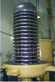
12 Stage Multiplier Stack
12 Numbers of Cockraft Walton scheme based fully balanced multiplier stacks were cascaded in series to generate - 750 kV DC from 40 kV / 40 kHz sinusoidal input. Low loss 40 kV ceramic capacitors, high voltage avalanche type 15 kV diodes modules and high voltage bulk type series limiting resistance modules were connected in series to achieve 80 kV high voltage rating of each multiplier stack. A high voltage divider was developed using high voltage resistance to readback the generated High Voltage. Two numbers of 45 kV / 40 kVA High voltage transformers were developed to boost the inverter output and feed the multiplier stack for further boosting to -750 kV. Two numbers of 48 mH, 45 kV ferrite cored inductors were developed to compensate the high distributed capacitance of the HV transformer. The multiplier stack was sealed in a SF6 filled (at 5 atmosphere) pressure vessel to achieve the required insulation levels.
|
|
|
Multiplier Stack of 750kev DC accelerator |
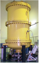
Assembled DC Accelerator |
45 kW Converter
The scheme consisted of a input transformer feeding a three phase SCR bridge and L-C filter. The DC output feeds 40 kW / 40 kHz ZVS resonant inverter. The inverter in turn feed the power to 15 stage Cockcroft Walton based multiplier stack through ferrite cored 45 kV high frequency step up transformer, for high voltage generation.
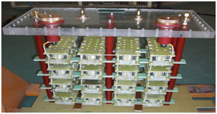
40 kW Resonant Inverter
It utilized an IGBT based full bridge ZVS resonant inverter feeding an LCLC resonant network. The distributed capacitance of the 45 kV high voltage transformers was compensated by high voltage Inductors connected on the secondary side of the HV transformers. The inverter operated under ZVS for complete range of load variation. An arc detection and tripping scheme has also been incorporated in the circuit.
|
High Frequency High Voltage Inductor |
Filament Power Supply
The current controlled filament supply (20 A / 5 V) followed buck converter scheme and was fed through a high voltage transformer connected to the last stage of the Cockcroft Walton multiplier. The supply was floating at -750 kV w.r.t. earth. The 40 kHz AC input to the supply was derived from the top of the multiplier stack through a step down secondary of a high voltage transformer. The filament current was remotely controlled and monitored from ground potential through fibre optic channels.
Fiber Optics based Remote Control System for Filament Control
A fibre optics based system was developed to control and monitor the filament supply floating at 750 kV with respect to earth. Frequency to voltage and voltage to frequency converters along with pulse width modulation was used to transmit and receive the analogue signals for current and voltage of the Filament supply. Opto transmitters and receiver modules with bandwidth of 5 MBD were used for conversion of electrical to optical and vice versa over a length of about 50 metres.
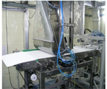
Digital Irradiation Pass Counter
A fully digital counter was used to monitor and control the number of passes of the product to be irradiated. It takes the inputs from proximity switch connected on the conveyor system and controls the operation of the conveyor drive system.
41 Channel Remote Transmission and Reception through Fiber Optics
In the earlier version of the accelerator, the Filament and Bias supplies of the triode type electron gun were controlled and monitored remotely through fibre optics by using fibre optics based 41 channel transmitter and receiver system. All the control and monitoring signals were transmitted and received through a single fiber optic cable individually. Parallel to serial and serial to parallel circuits and systems were developed which used ADC and DAC chips for analog to digital and vice versa conversions.
A microcontroller 8051 and PC based control system communicating over serial protocol RS232 for operating the Accelerator
A 8051 based control system was developed that used input /output cards, ADC/DAC cards and opto isolation cards to communicate with different subsystems of the accelerator.