Converter Development Lab (CDL)
Power Converters for Indus-1
- Specifications and number of the magnet power converters developed by CDL
- Microtron Dipole Magnet Power Converter
- TL-1 Combined function steering coil power converters
- Booster Dipole Magnet Power Converter
- Booster Vertical Steering Coil Power Converters
- Transport line-2 Steering coil power converters
- Indus-1 dipole magnet power converter
- Indus-1 steering coil power converters
The specifications and number of the magnet power converters developed by CDL for microtron, booster, beam transport-line (TL2) and Indus-1 respectively are listed in the following table:
System |
Magnet |
Type of output |
PS Output |
Stability
(ppm) |
No. of
PS |
Vmax(V) |
Imax(A) |
Microtron |
Dipole |
DC |
50 |
240 |
± 100 |
1 |
Transport Line-1 |
Combined function steering coils |
DC, Bipolar |
20 |
10 |
± 500 |
2 |
Booster |
Dipoles and Quadrupoles (6 Dipoles MW + 6 QF W1 + 6 QD W1) |
Ramped at 1 Hz |
800 |
1000 |
± 100
@ Flat top |
1 |
VSC |
Ramped at 1 Hz |
20 |
20 |
± 500 |
6 |
Transport Line-2 |
Steering coils |
DC, Bipolar |
36 |
6 |
± 1000 |
11 |
Indus-1 |
Dipoles |
DC |
140 |
800 |
± 100 |
1 |
Steering coils |
DC, Bipolar |
20V
40V
5V |
3A
5A
10A |
± 1000 |
12 |
The abbreviations in the above table stand for:
| Dipoles MW: |
Main Winding |
| QF W1: |
Focusing quadrupole primary winding |
| QD W1: |
Defocusing quadrupole primary winding |
| VSC: |
Vertical steering coils |
The power converters have been developed using different schemes since the ratings and stability requirements are diversified. A brief description of schemes used to develop these power converters is as follows.
Microtron Dipole Magnet Power Converter
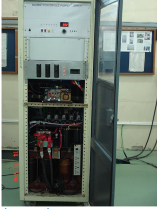
As the name signifies, this power converter energizes the dipole magnet of Microtron. A 12-pulsed SCR pre-regulator feeds power to a transistorized series-pass regulator. A close loop feedback system maintains constant output current. Major components are water-cooled. A current cycling system helps in keeping same current at constant magnetic field. An azimuthal system allows different currents in two halves of the dipole magnet. High stability of current over long time is very important for maintaining beam quality from Microtron.
|
Microtron Dipole Magnet Power Converter |
TL-1 Combined function steering coil power converters
These two power converters rated for 20V/10A are a new addition in Transport line -1 just after Microtron. Salient features of these power converters are: unity power factor at the input, bipolar load current, smooth transition from one polarity to other, and higher efficiency. Power stage consists of a boost converter at the input to ensure unity power factor, a full-bridge inverter to achieve isolation as well as required voltage at the load followed by full bridge inverter for changing polarity of the load current.
Booster Dipole Magnet Power Converter
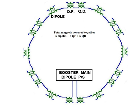
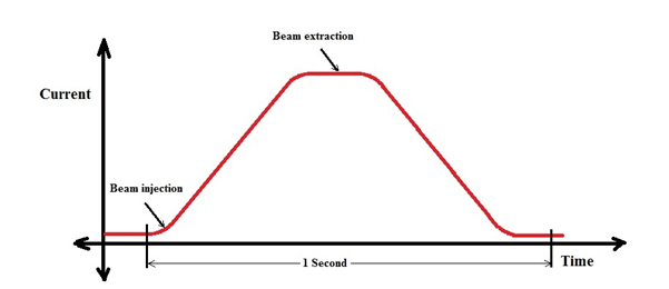
In booster ring, trapezoidal current passes through 6 dipole magnets and 6 pairs of QF and QD magnets with a repetition rate of 1 Hz. Current is ramped up from 28 A (corresponding to injection beam energy from Microtron) to higher values (corresponding to injection energies of Indus-1 and Indus-2) in approximately 400 mS, held there for 100 mS and forced to decrease thereafter so that injection for the next cycle is possible after 1 Sec. The powering scheme of booster magnets is shown here. Also shown is the booster current profile.
|
Booster magnet powering scheme |
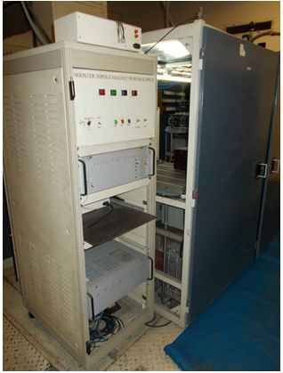
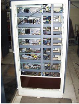
In booster dipole power converter, two three-phase SCR bridges are put in series constituting a 12-pulsed rectifier system. Bi-directional voltage at the output necessitates a bipolar capacitor bank. A complex feedback loop system provides the necessary current wave shape and maintains the needed current stability. Precise timing of the current waveform is crucial for accurate injection in booster ring. All other power converters in Booster ring (adjustment coils for quadrupole magnets, horizontal and vertical steering magnets) follow the same current profile.
|
Booster dipole magnet power converter |
Booster Vertical Steering Coil Power Converters
These power converters feed five independent vertical steering coils with Booster Ramp Current Profile (peak current rating of 20A), are true bipolar in nature and can operate at very close to zero current. They are developed using linear power amplifier schemes. They also follow the ramp current profile as other booster magnets.
|
|
Booster Vertical Steering Coil Power Converters |
Transport line-2 Steering coil power converters
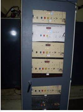
These 11 power converters are meant to energize independent steering coil magnets for horizontal and vertical correction of electron beam. They are also bipolar in nature and developed using switching techniques.
|
TL2 steering coil power converters |
Indus-1 dipole magnet power converter
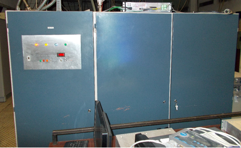
This power converter rated for 140V/800A DC is used to energize 4 dipole magnets in Indus-1 ring. The required current stability is ±100 PPM. This power converter also uses a 12-pulsed SCR regulator and filter with associated feedback loop to achieve these parameters. All power components – SCRs, transformer, and filter inductors are water-cooled. As usual, the power converter is fitted with standard safety features such as- water failure, overcurrent, overvoltage etc. As with other magnets in Indus-1 ring, the dipole magnets also undergo a cycling pattern, where the currents of all power converters are cycled around the required value in a pre-determined way so as to achieve set magnetic field at same current.
|
Indus-1 dipole magnet power converter |
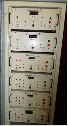
Indus-1 steering coil power converters
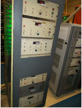
These power converters energize independent steering coils as well as the coils mounted on sextupole magnets in Indus-1 ring. These are bipolar in nature and maximum current is 3A, 5A, and 10A for three different types of power converters. These power converters have been developed using different topologies- like Switching mode techniques as well as linear transistorized system.
|
Indus-1 steering coil power converter |