Magnetic Layout of Indus-2 ring
Its unit cell has two 22.5 bending magnets, a triplet of quadrupoles for the control of
dispersion in the achromat section, two quadrupole triplets for the adjustment
of beam sizes in the long straight sections and four sextupoles in the achromat
section for the correction of chromaticities. An advantage of this lattice is
that the two 2 m gaps between the focussing and defocussing quadrupoles in the
achromat section provide a lot of space for accommodating beam diagnostic and
vacuum devices. A similar structure with a gradient in bending magnets has been
adopted for the synchrotron radiation source ELETTRA at Trieste (Italy). Though
the gradient has some beneficial effects on the beam optics, we have chosen
normal parallel edged magnets to avoid fabricational problems associated with
gradient magnets. Of the eight 4.5m long straight sections, one will be used
for beam injection and two for RF cavities and the remaining five for insertion
devices. Presently, two wigglers are planned to be installed in the ring. The
remaining three straight sections will remain unused for some time leaving some
scope for further development of the machine. It is felt that with passage of
time and also as a result of the experience on Indus-2, users might come up
with some additional radiation requirements or there may be a major
breakthrough or development in the science and technology of insertion devices.
To be able to meet the future aspirations and to keep pace with new
developments, new insertion devices can be planned and built and these can be
accommodated in the straight sections left unused.
The operating point of the ring has been selected by avoiding the major resonance lines viz 3x = 4 & 5, 2x = 3, x + 2y = 3, x -2y = 1 etc. The tune per superperiod is chosenas (1.15, 0.65). From the radiation brightness and beam dynamics considerations of wigglers and undulators the radial and vertical functions in the insertion straight sections are selected in the vicinity of 14 m and 2 m respectively. The length of the straight section between the focussing quadrupole and the defocussing quadrupole of the achromat has been adjusted to obtain a good decoupling of x and z and a small beam emittance. A thorough study of the lattice has been carried out using an indigenously developed program. The lattice functions at the tune point (9.2, 5.2) are shown in Fig.2.
Figure 2: Lattice functions of Indus-2
At this point, the beam emittance
will be 3.7210-8m.rad at 2.0 GeV with zero dispersion in
the insertion section. The parameters of Indus-2 at this tune point are given
in the Table-1. The machine can be operated with a beam emittance of 2.210-8m.rad allowing a dispersion of 0.2m in the
insertion section with a moderate change in beta functions. For the correction
of chromaticities, two families of sextupoles are used per superperiod. As an
x-ray source, Indus-2 is envisaged to provide radiation from bending magnets
and wigglers. The beam energy of 2.0 - 2.5 GeV is adequately high to produce
powerful x-rays from these devices. The spectral flux and brightness for the
bending magnets, multipole wiggler and wavelength shifter at 2.5 GeV are
plotted in Figs. 3 (a & b). A coupling constant of 10% has been taken into
consideration for the calculation of beam brightness. When the coupling
constant is lower, the brightness will be higher.
Fig.3 : (a) Photon
flux and (b) Brightness as a function
of Photon energy of Indus-2
For
brightness calculations of bending magnets the source point has been taken as
the centre of the magnet. In bending magnet sections, the radiation ports will
be provided at 5° and 10° from the edge of the magnet facing the electron beam.
Therefore in one superperiod, four ports will be available for tapping
radiation. Since the beam sizes are not symmetric about the centre of the
magnet, the values of the brightness will not be the same at these four ports.
The brightness at each of these ports will also be somewhat different from its
value at the centre of the magnet. It is estimated that the values of the
brightness for three ports i.e. 5° and 10° ports of the first magnet and 10° of
the second magnet will be within 10 % of the brightness at the centre of the
magnet whereas the brightness at the fourth port i.e. 5° port of the second magnet will be around 65 % of the
brightness at the centre of the magnet.
It is possible to operate Indus-2 at any energy
between 600 MeV and 2.5 GeV. At lower energies, the emittance of the ring will
be much lower and source can be used to produce radiation of much higher
brightness.
The electron beam extracted from the synchrotron
will be injected into Indus-2 in the horizontal plane. The synchrotron will
provide two bunches each around 1 ns long separated from each other by nearly
30 ns at the required energy at a repetition rate of 1-2 Hz. After injecting
several pulses at 600-700 MeV to accumulate 300 mA, the beam will be
accelerated to 2-2.5 GeV by slowly increasing the magnetic field of the bending
magnets. The beam will be injected in the horizontal plane via two septum
magnets (one thick and another thin one) by a multiturn injection process in
one of the 4.5 m long straight section by employing a compensated bump which
will be produced by means of four kickers.
To fill
a current of 300 mA in Indus-2 at the repetition rate of 1-2 Hz, a beam
lifetime of at least half an hour is required. At the peak energy, beam
lifetime of several hours is required for synchrotron radiation experiments.
The beam lifetime is mainly decided by two processes, Coulomb scattering within
the electron bunch (Touschek scattering) and scattering of electrons with the
residual gas molecules. Assuming that
the beam circulates in an ultrahigh vacuum environment having vacuum better
than 10-9 mbar consisting of nitrogen gas and the limiting
acceptance from both the transverse planes, the total beam lifetime is around
12 hours which is adequate for all the applications at 2.5 GeV. At 2.5 GeV the
beam lifetime is ~ 18 hours. An RF voltage of 1.5 MV is required to achieve
this lifetime at 2.5 GeV. The cavity peak voltage will be ramped in order to
capture the maximum beam. During the voltage ramp, the synchrotron tune will be
kept constant. The required voltage will be generated at the frequency of
505.812 MHz by employing four RF cavities.
The 2.5 GeV synchrotron radiation source
Indus-2, is in advanced stage of construction.
All the sub systems of Indus-2 are progressing as per fabrication
schedule in various industries. It is expected that by early 2003 Indus-2 will
be ready for commissioning. A prototype dipole magnet of field 1.5 Tesla has
been fabricated, assembled and tested. The magnetic characteristics exhibited
by the prototype dipole magnet are better than what is required from the
lattice design considerations. Figure 4 shows the assembled dipole magnet. The
remaining 15 cores of dipole magnets are being fabricated at M/s Godrej,
Mumbai. All the cores of Quadrupole and Sextupole magnets have been fabricated.
Coils of all the magnets Dipole, Quadrupole and sextupole have also been
fabricated and prototypes of quadrupole and sextrupole magnets have also been
assembled and characterized. Figure 5 shows the assembled sextupole magnet
being characterized on a magnet field-mapping machine.
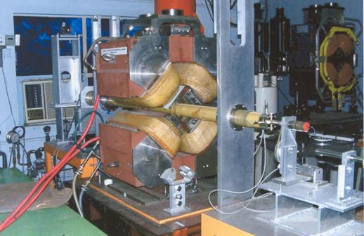
Fig.4 : Quadrupole Magnet for Indus-2
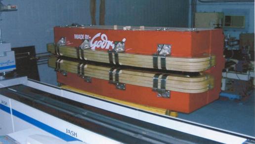
Fig.5 : A prototype 1.5 Tesla Dipole
magnet for Indus-2
Seventeen
sets of complex shaped, high profile accuracy dipole vacuum chambers have been
machined on a 3-axis CNC Profiler machine at HAL, Nasik. A prototype dipole
vacuum chamber has been welded and tested for vacuum and vacuum leak tightness
of 2x10⁻¹⁰ Torr lit/sec has been obtained. Figure 6 shows the welded
assembly of a dipole vacuum chamber.
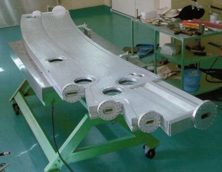
Fig. 6 : Welded Assembly of a Dipole
Vacuum Chamber for Indus-2
The 64
kW Klystron and high power circulators have been received and tested at full
power at the suppliers site. Two numbers of RF cavities have been fabricated
at ELLETRA, Italy and preliminary testing has been carried out at the
suppliers site. Low Level RF electronics for Amplitude and phase control for
cavity gap voltage has also been developed.


