Accelerator Controls & Beam Diagnostics Division
Slow Orbit Feedback System (SOFB)

Indus-2 SOFB system is there to correct the slow varying orbit deviations so that electron orbit remains within allowed limits. This in turn helps to ensure that the photon beam on various bemalines remain stable such that several users on these different beam lines get the photon beams with designed stability. SOFB utilises 56 BPIs, 40 correctors in vertical plane and 48 correctors in horizontal plane. Not all the BPIs are used all the time, some are redundant. The system may work without some of them with minor functional degradation. So basically it is a MIMO system of 40*56 and 48*56 in horizontal and vertical planes respectively.

 
SOFB loop architecture (with IP addresses details) Beam Position (BPI) data before and application of SOFB
Fig1: SOFB loop architecture (with IP addresses details) [Full Size Image] Fig2: Beam Position (BPI) data before and application of SOFB [Full Size Image]
All the steering coils are controlled by power supplies which in turn are controlled through VME equipment control layer i.e. Layer-3 of the overall 3-layer control system architecture adopted for most of the control systems of Indus-2 sub-systems. All layer-3 VME stations are installed on equipment gallery of Indus-2 and near to the steering magnets to be controlled. The supervisory control layer i.e. Layer-2 is responsible for communicating the provided current settings to the layer-3 over profi-bus. The layer-1 or uppermost layer consists of SOFB controller application running on real time operating system (RTOS) which is connected to layer-2 through Ethernet. BPI data from Bergoz analog BPIs (40 Nos) and Libera brilliance+ digital BPIs (16 Nos) is accessed through separate channels. Digital BPI data is directly available on ethernet from the BPI electronics unit (Libera Brilliance+) over UDP at 10Hz rate. This data is received by DBPI server application by parsing incoming UDP data and sub-sampling at 1 Hz. The data is then passed to SOFB controller that sits in the RT environment. The data from analog BPIs are received via 3-layered architecture. The Bergoz electronics passes the data to VME layer-3 station after processing in analog domain. Both these type of units are kept at equipment gallery. The VME layer-3 consists of VME controller and VME ADC boards. The digital data is then transmitted to VME Layer-2 station through profi-bus. The layer-2 gives this data to SOFB controller over Ethernet via UDP packets at 1 Hz.
 
Main GUI showing ON/OFF state and position error (mm) GUI showing system identification (SI) process through client GUI
Fig3: Main GUI showing ON/OFF state and position error (mm) [Full Size Image] Fig4: GUI showing system identification (SI) process through client GUI [Full Size Image]
 
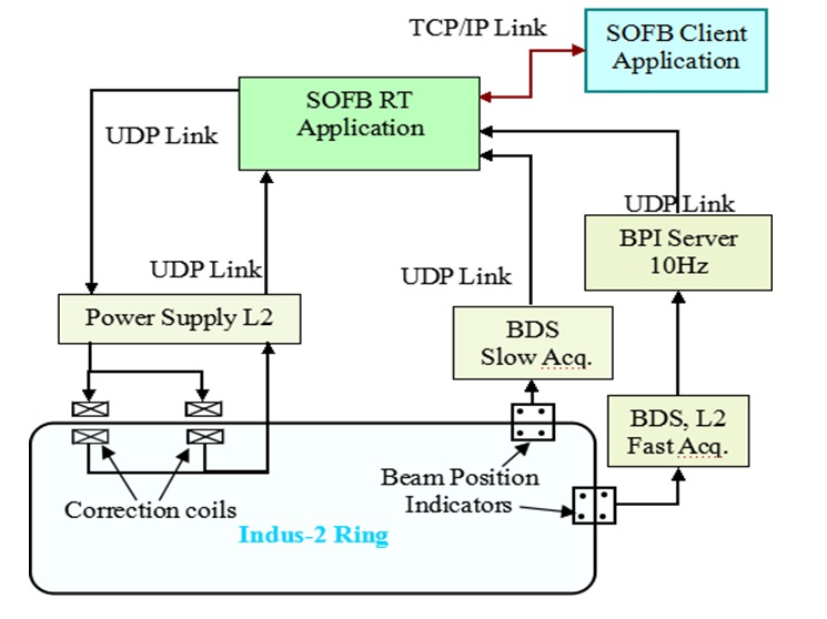
Model Predictive Control: A new, model based predictive control (MPC) has been implemented for the control of beam position around the ring at 56 BPI locations by using 40 vertical and 48 horizontal steering coils. The control is done through a Real Time (RT) controller PC put on Layer 2 which takes BPI data on per second basis from Beam Diagnostics System (BDS) at Layer 2 and updates the corrector PSs system at L2. So effectively a two layer control system is implemented which is an improvement from earlier version of SOFB where control was implemented on the L1 layer (User Interface Layer). The correction rate employed is once per 3 seconds (1/3 Hz). The correction range of SOFB is from few mm down to about 30 microns. MPC has the advantage of utilizing available correction strength of correctors effectively by optimizing the control sequence based on the present operating condition of the machine.
Best viewed in 1024x768 resolution