| Controls, Diagnostics and Beamline Instrumentation Division |
| Magnet Power Supply Ramping Verification System |
|
The beam in Indus-2 SRS is ramped from injection energy to an energy of 2.5 GeV. The overall ramping process is implemented in multi-layer & distributed control system of Indus-2. Increasing the beam energy requires ramping of magnetic fields of total 117 magnet power supplies and 6 RF cavities synchronously.
This process involves ramp profile data generation for each power supply based on user defined profile breakpoints and then synchronously setting these
profiles as per user defined clock rate.
Deviation, if any, occurring during the ramping process, could be the potential cause of beam-loss/partial beam-loss, orbit distortion or
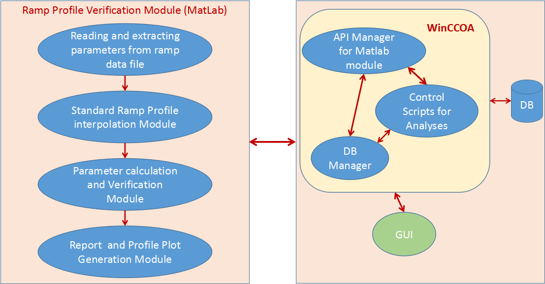
tune shift. To overcome the difficulty in quickly identifying such a deviation, which otherwise involved tedious manual process by analyzing the data corresponding to 117 power supplies for the ramping duration, a ramping verification system is developed. The system provides automatic verification of the correctness of ramping of all 117 power supplies participating in ramping along with and genration of the reports. This is implemented using SCADA and Matlab modules. Various sequential tasks are executed by these coordinating software modules as depicted in figure-1
Ramping verification algorithm
The algorithm was developed to verify that each Magnet Power Supply (MPS) has followed the Ramp profile as per the standard ramp file selected .
The system verifies that :
- All the required Power Supplies had been selected for Ramping.
- All the selected Power Supplies had participated in Ramping.
- Ramp profile matched the standard profile.
Verification which is done using MATLAB modules, involves checking of deviation of key parameters viz. initial value, final value and profile correlation factor beyond the tolerance limits. The tolerance limits were finalized by analyzing the historical ramp data and the algorithm was tested with archived, online and simulated ramp data.
Features
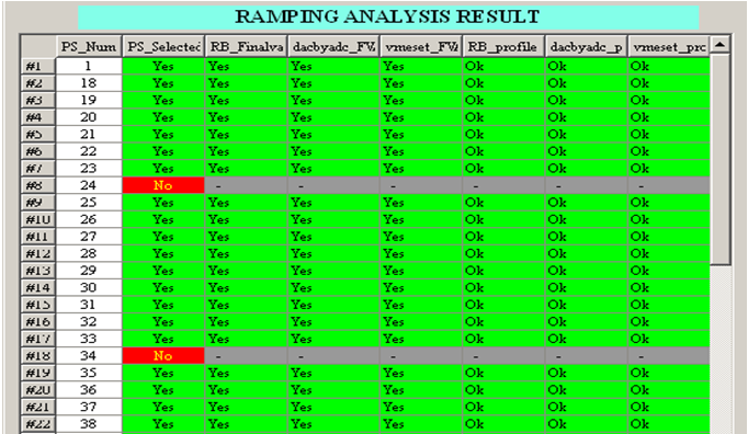
The system is modular and has configurable tolerance limits. The system provides verification status in the form of a report depicting the
pass/fail status of individual MPS for all three signals viz power supply current read-back, reference read-back and digital set as shown in
figure-2. A detailed report indicating the faulty key parameter(s) is also available, in case of any problem, which helps in quick
identification of the faulty system.
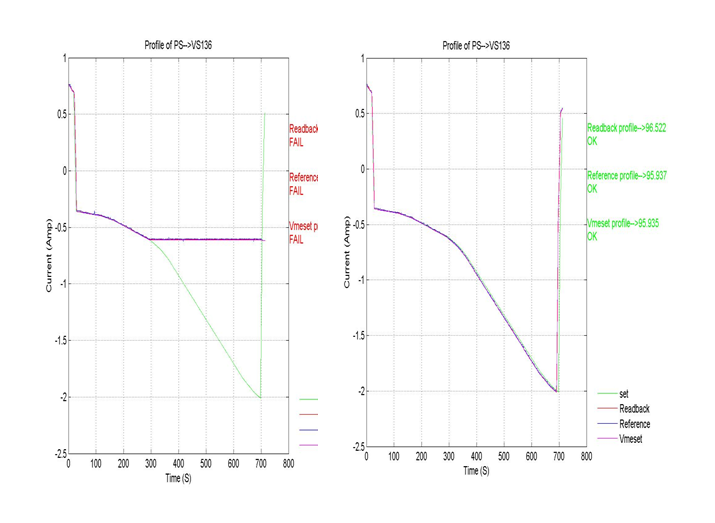
The report also provides plots of above signals (Figure-3) for all power supplies. The various verification parameters are stored in database.
|
 |
 |
 |
| Figure1: Overall ramping verification process[Full Size Image] |
Figure2: WinCC OA Panel showing overall Verification status of all PS to the operator [Full Size Image] |
Figure3: Signal plot for Vertical Steering Coils with ramp profile (a) Not OK (b) OK [Full Size Image] |
| |
|


