| Controls, Diagnostics and Beamline Instrumentation Division |
| Magnet cycling verification system for Indus-2 |
|
Repeatable and history free magnetic field profile of various magnets is a prerequisite for repeatable operation of Indus-2. This is achieved by cycling the current of Magnet Power Supplies (MPS) flowing through the magnets in every beam injection cycle. Cycling of magnet current in a well defined often step by step decreasing fashion helps to demagnetise the magnet core. Since cycling is important for repeatbility, therefore verification of the correctness of cycling process itself is an important aspect of day-to-day machine operation and a confidence building measure.
Earlier, such verification had to be carried out by the tedious manual process by analyzing the data corresponding to 138 MPS pertaining to the cycling duration. A system providing automatic verification of the process and reporting the results is developed and put in regular use. The overall verification system consists of sequential execution of various tasks by interconnected software modules developed in SCADA and Matlab which is depicted in figure-1.
Verification algorithm
The cycling of MPS has some key parameters viz. number of cycles, initial value, maximum flat top value, rise and fall slope etc. Verification process involves checking deviation beyond tolerance limits for the key parameters and also to detect presence of any spikes & glitches in the signals. An algorithm is designed and developed in the form of various MATLAB modules to achieve the same. The tolerance limits were finalised by carrying out cycling experiments on the Indus-2 machine by varying various key cycling parameters and subsequently analyzing their effects on the beam.
The developed algorithm was tested with archived, online and simulated cycling data.
Features
The software is flexible and has configurable tolerance limits & enabling/disabling of individual MPS for verification.
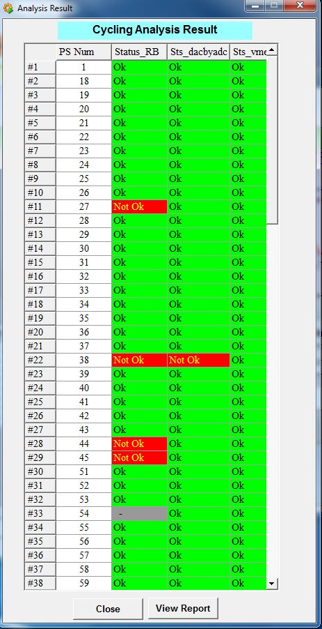
The system provides verification status in the form of a report depicting the pass/fail status of individual MPS for all three signals viz power supply current read-back, reference read-back and digital set as shown in figure-2. A detailed report indicating the faulty key parameter(s) is also available, in case of any problem, which helps in quick identification of the faulty system.
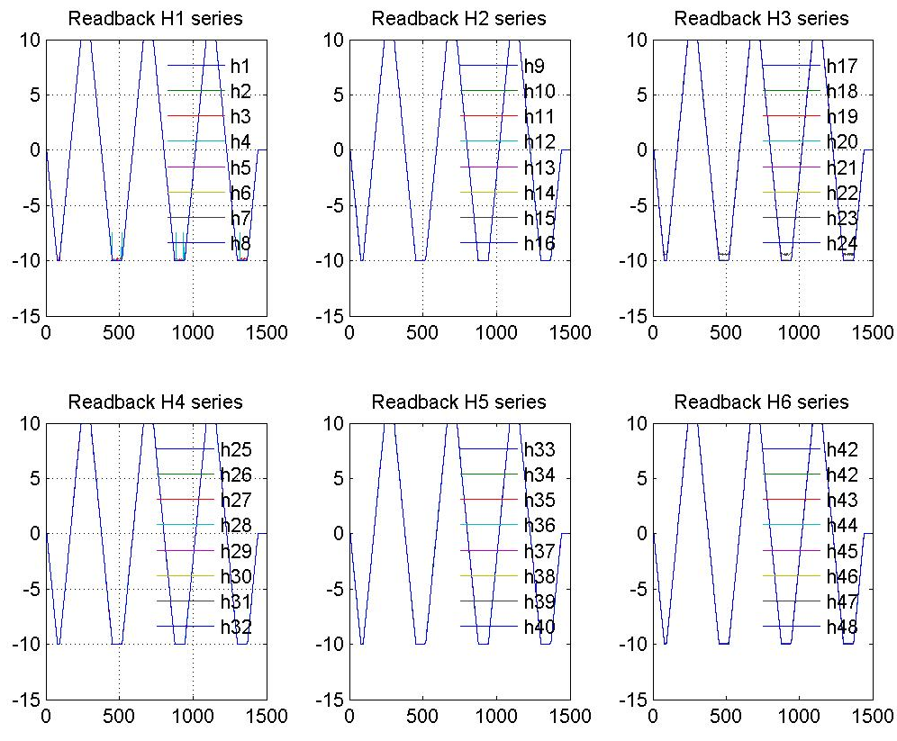
The report also provides plots of above signals (Figure-3) for all power supplies. The various verification parameters are stored in a csv file and their history is also maintained.
|
 |
 |
 |
| Figure1: Overall cycling verification process[Full Size Image] |
Figure2: Cycling Analysis Results [Full Size Image] |
Figure3: Signal plot for Horizontal Steering Coils [Full Size Image] |
| |
|


