| Controls, Diagnostics and Beamline Instrumentation Division |
| Control system for Indus-2 Undulators |
|
In Indus-2 three undulators have been installed. The control system for these undulators called U1 U2 and U3 is developed and remote operation of undulators from control room is enabled using software developed in LabVIEW. Special emphasis is given to planning and testing of various safety interlocks.
The control system is architected as a distributed and modular as shown in figure 1. It has an intermediate software layer to support simultaneous monitoring and control of U1, U2 and U3 device controllers as well as to have capability to augment other insertion devices which would be installed in future. It is developed for ensuring proper interfacing with Indus-2 machine control system.
The control system development included communication interfaces, protocol for communication, software and hardwired safety interlocks and it facilitated remote monitoring of various parameters. A dedicated ID server software is developed in LabVIEW, which interacts with the undulators over ethernet link. This software forms an intermediate layer between machine control system and ID control system. Some parts of the software server are shown in the figure2. This software runs from server room over accelerator network (AccNET) and provides necessary data to client GUI which runs in main control room. Typical data update rate of the software is 2 Hz.
The ID server software has various features such as automatically restricting the undulator controls by enabling the control room GUI in view only mode, thereby ensuring undulator jaws are not moved until the software receives ‘Beam Ready’ from the machine control system. This software displays undulator parameters, interlocks and alarms in the main control room GUI (Figure 3) and performs data logging of these parameters in the central database of Indus-2.
The temperature, water flow & beam position interlocks are enabled from main machine control system taking into account various machine states. These are implemented in different layers of control system in machine safety interlock system (MSIS) and beam line front end (BLFE) control system. IDBPI based beam position interlock is enabled under certain machine states defined by ‘Beam Ready’ signal. It ensures that this interlock is effective under critical condition of beam mis-steering which might occur during undulator jaw movement. Operation of undulator is enabled only when ‘Beam Ready’ state is asserted by Indus-2 control system.
Three independent Undulator controller racks (for U1, U2 and U3) each having main PLC of Beckhoff CX502x series Embedded PC, 4 servo motor drives, touch panel and interlock relays, are installed on Indus-2 equipment gallery and the secondary racks are mounted on the undulator body itself. Equipment rack is connected to the secondary rack with an EtherCAT cable for communication, a cable for providing 24V DC to the secondary rack and a cable for the safety signals. The hardwired interlock signals are connected from equipment rack to the machine safety interlock system (MSIS) rack using an 8-pair twisted shielded cable in fail-safe manner. On the MSIS rack a fast interlock module is mounted. This CPLD based module keeps dedicated vigil on undulator interlock signals such as Undulator - OK, temperature and cooling water flow etc. The CPLD module asserts fast signal for tripping the Indus-2 RF in case any of the critical interlock fails. This signal kills electron beam to bring the machine in safe state.
|
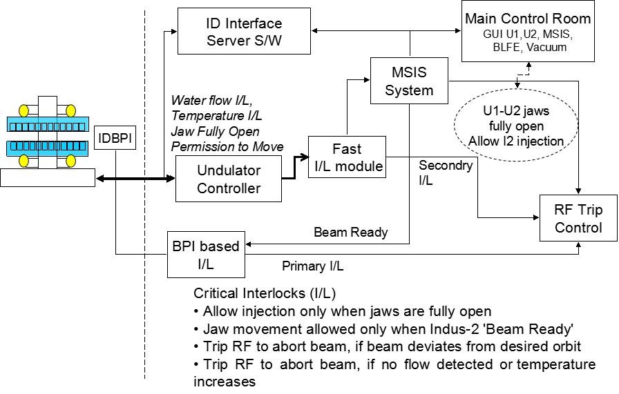 |
Figure1: Block diagram of Control System and Interlocks for U1 and U2 undulators[Full Size Image]
|
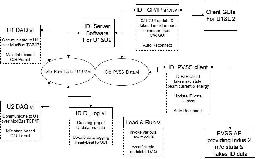 |
Figure2: Block diagram showing ID interface server software and its components [Full Size Image]
|
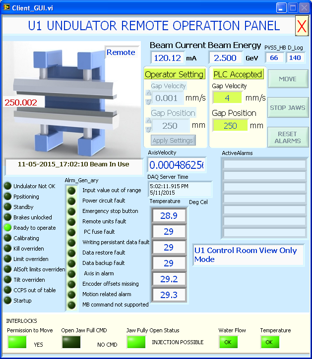 |
| Figure3: A screen shot of Undulator GUI [Full Size Image] |
| |
| |
|


