| Controls, Diagnostics and Beamline Instrumentation Division |
| Agent based control system for Beam-line (BL) alignment |
|
Orbit bumps in the electron orbit in SRS are generally provided for alignment of SR at BL experiment stations. Corrector or steering magnets are used on top of other magnet optics. These correctors are used by SOFB as well. Until now, local bump was provided using SOFB system. Subsequently predictive facilities were provided to the operator in the SOFB application for easy visualization of changing reference orbit. However the process becomes iterative and a need of automatic and intelligent algorithm was felt.
Application of local electron orbit bump for various purposes is often needed in an SRS. It is applied in such a manner that the desired local electron orbit profile in the ring is achieved with least affect elsewhere. This in turn requires accurate system model. However, in accelerators, parameters change with the operating point and also an accurate model of the system is not possible for such a dynamic system. Even slight deviation of model from system dynamics may result in drastic side effects on the beam. So, to minimize the efforts put into orbit correction and to minimize disturbance outside local bump every time the manual tuning activity is required, an intelligent agent based solution for finding bump parameters, with self skill update capability, is planned to be implemented into Indus-2 orbit control though. This system helps in the aligning the electon beam for a particular BL without disturbing other nearby BLs. A local closed bump is given around the BL and a constraint heuristic learning is deployed to track the changing operating conditions of the system to learn and update the control agents for orbit control. The criticality of the application demands a stable, reliable and robust operation of the proposed software. Checks are adopted into the application and verification and validation tests would be carried out before final deployment.
Below figure is a snap of the client application GUI highlighting its various parameters for selected BL (its BL 12 here), skill set graph, local corrector current graph, bump and leakage graph and interface button for activating various modes of operation, like simulate bump requirement at correctors and BPIs through changing position at BL sample, apply the simulated request interactively (with learning, if required), apply request quickly and apply request manually (step by step).
The figure shows, the local bump is achieved with tolerable bump leakage i.e. 6.3 µm for achieving a bump height of around 250 µm and corrector values are within constraint boundary of ±6A. As per system model, a position change of 640 µm was required at BL 12 sample point which was achieved by the application without any learn cycle.
|
| |
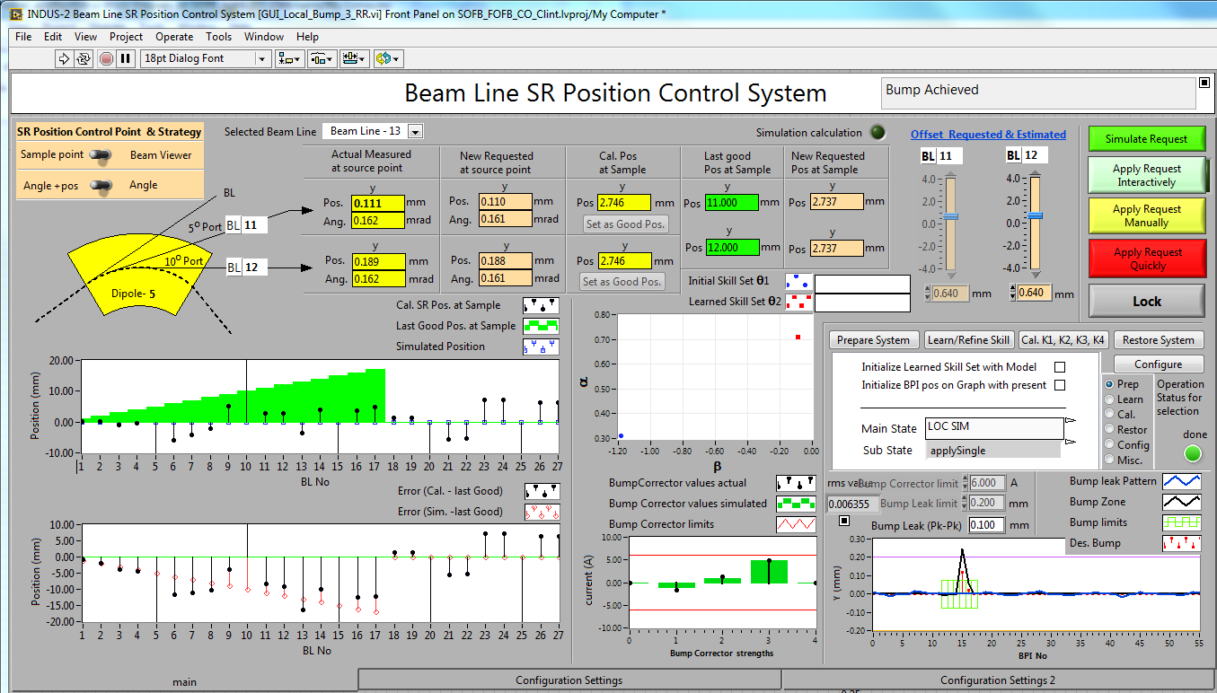 |
| Fig.1: Beamline SR Position Control System[Full Size Image] |
| |
|


