| Controls, Diagnostics and Beamline Instrumentation Division |
| I-1 Timing Control System |
|
The role of Indus-1 Timing Control System (I1- TCS) is mainly to generate timing trigger instants required for Indus-1 machine operation. I1-TCS controls & monitors 08 Pulsed Power Supplies (PPSs). Timing signals are given to PPSs which energize the pulsed magnets to control beam movement. Besides, TCS also controls/monitors all the PPSs using different analog & digital signals.
The system went through upgradation after which following features are provided - isolation among channels, provision of both Fibre optic & copper cable interface for trigger and analog signals, replacement of independent modules via rack mountable cards for increased modularity and easier maintenance, miniaturization of cables/connectors, debugging facility over ethernet based communication on SCADA etc.
Architecture:
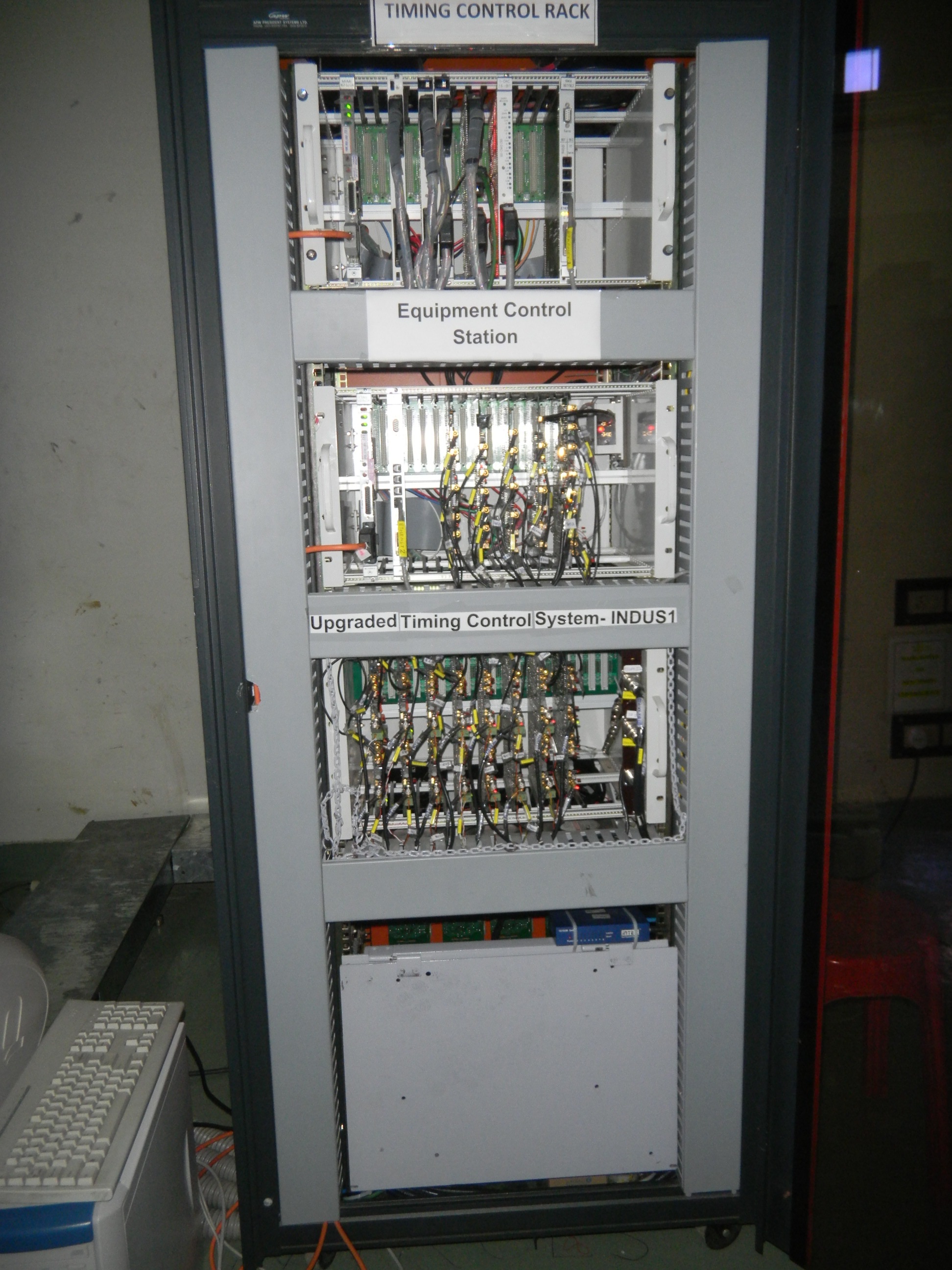
I-1 TCS has two layer (L1 & L2) architecture. The equipment interface layer (layer-2) is built with VME bus based modular system as Equipment Controller and other electronics hardware within an Equipment Control Station (ECS) located in the field. Equipment Control Station (ECS) handles field interface signals like analog/ digital I/O signal and Timing trigger signals. A non VME sub-rack holds the cards for isolated trigger signal interface. Fig.1 shows the ECS. This L2 station is linked to operator console at Layer-1 in the control room over Ethernet.
Functionality:
Input / Output (I/O) signals are digital status/control & analog readback/reference set signals of PPSs and other system related signals. There are ~200 I/O and trigger signals.
FPGA based delay generator boards generate the required delayed trigger signals with 1ns resolution. The trigger siganls are synchronised with respect to the 1 Hz Master Trigger which is generated at the injector Microtron timing.
Different operating modes of machine demand enabling/disabling of relevant signals manually/automatically in I-1 TCS. Trigger signals are qualified with machine interlock.
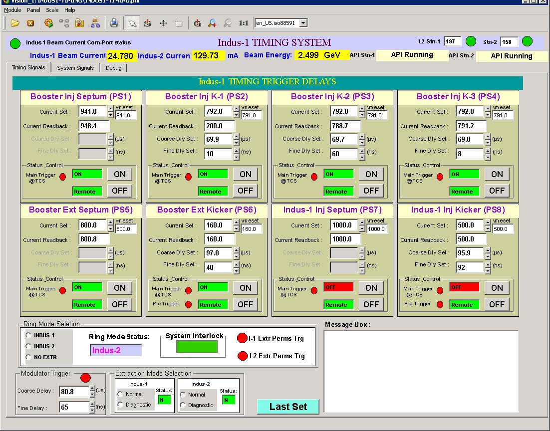
This timing control system is operated remotely from SCADA software interface where information of all signals is available on Graphical User Interface (GUI). The parameter history data are stored in SQL data base with WEB display facility. Fig2. Shows the a GUI panel.
|
 |
 |
| Fig.1:
Equipment Control Station of upgraded Indus-1 TCS [Full Size Image] |
Fig.2:
GUI of Indus-1 TCS [Full Size Image] |
| |
|


