| Controls, Diagnostics and Beamline Instrumentation Division |
| RF control system |
|
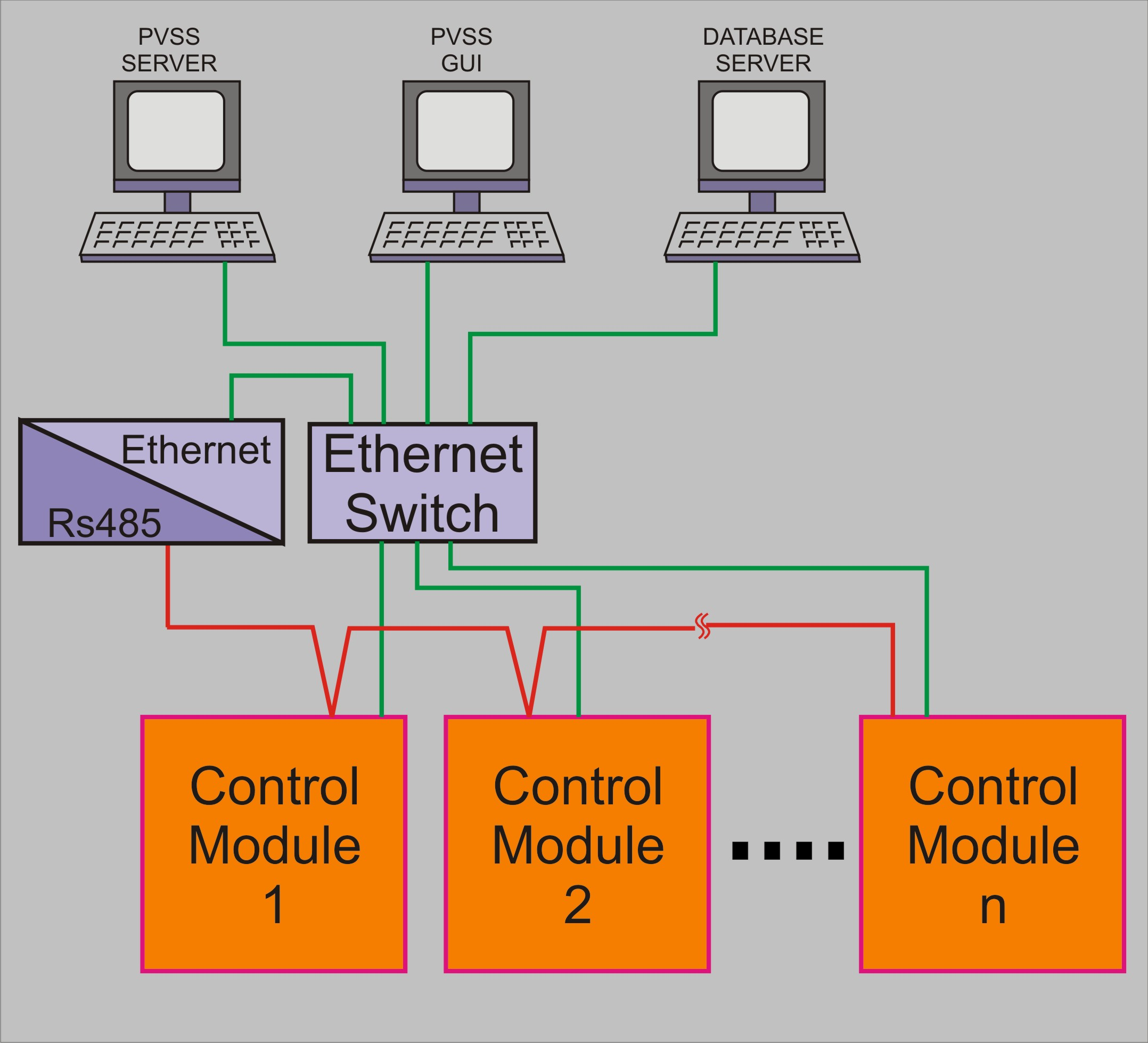
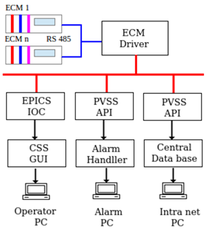
In Indus-1, the RF system comprises of three sub systems viz Booster Ring (BR), Storage Ring (SR) and RF Knock Out (RFKO) system and Ion Clearing (IC) system. The Booster is common for both Indus-1 and Indus-2 storage rings. The Indus-1 RF control system has been upgraded with a system with distributed and modular approach. The architecture is as shown in figure 1. Different Equipment Control Modules (ECM) are used to cater to interface with particular sub-systems indivdually or some combined together like BR, SR, IC+RFKO etc.
|
 |
 |
| Fig.1:
Architecture of Control System for Indus-1 RF subsystem.[Full Size Image] |
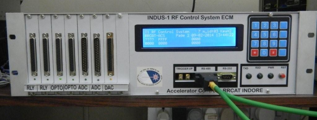
Fig.2:
Equipment Control Module of Indus-1 RF Control System. [Full Size Image] |
| |
Hardware
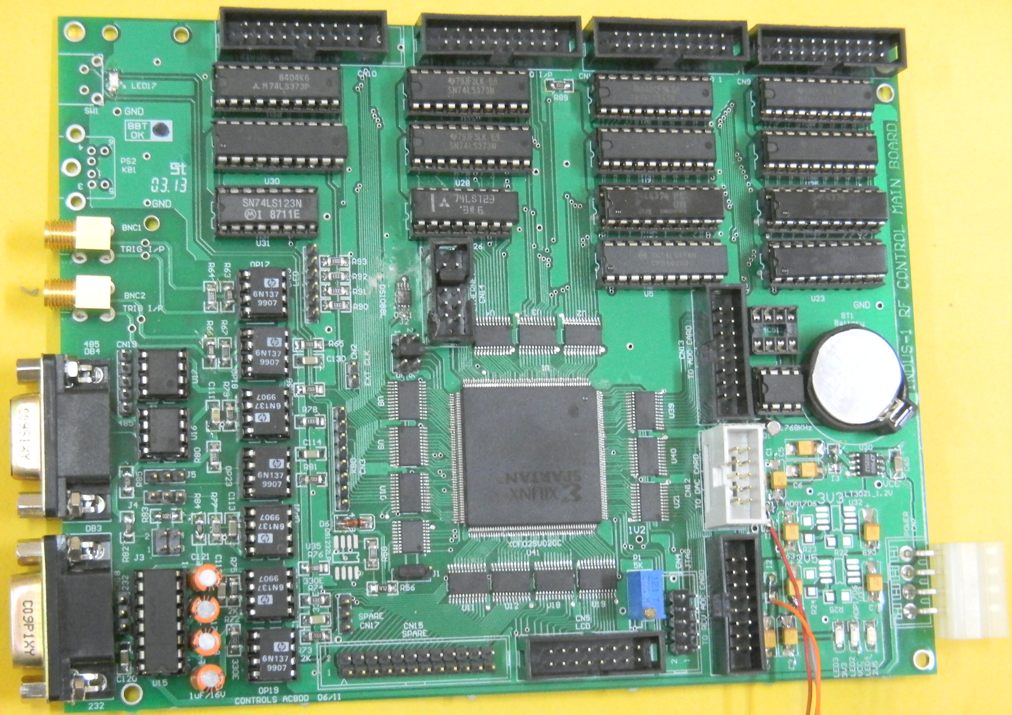
The ECM is designed to have several I/Os with LCD, 4x4 key pad, communication ports, trigger inputs and LED indicators. The circuit is realized using Xilinx Spartan 3 FPGA. In each ECM there are 32 control signals, 32 status signals, 32 analog inputs and 4 analog outputs available to interface with RF sub-system signals.
|
| |
| Main features: |
- Increased update rate ~10 Hz with RS485
- Less chances of whole system going down due to particular hardware failure on account of distributed and modular approach
- Local operation possible at Equipment Control Module
- Data can be viewed at ECM
- Ramp generation from ECM which gives fine setting of gap voltage at injection & final energy level
- Smooth switching from DC to Ramp and vice versa
- Online data retrieving from redundant network
- Programmable slope for smooth settings
- System last state restore feature on power up.
- 16 bit Data acquisition of all 16 channels @ 5K sampling
- External trigger input for event triggered sampling
- Time stamping using RTC
- Ethernet connectivity provision
|
 |
 |
| Fig.3:
Board developed for Indus-1 RF Control System[Full Size Image] |
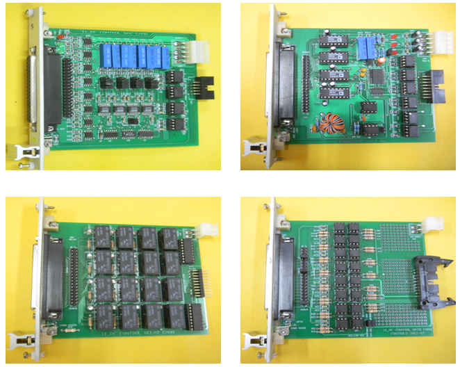
Fig.4:
Boards developed for Indus-1 RF Control System [Full Size Image] |
|
Software
The Indus-1 RF control system software is comprised of four main components 1. the EPICS IOC, 2. CSS GUI panels 3. WinCC OA API and 4. Data log files. Figure 5 shows the block diagram of Indus-1 RF control system Software and its logical connection to different system components.
The EPICS IOC is divided into four database definition files, one each for Analog readback, Analog setting, Status readback and Status setting type of devices. The IOC communicates to ECM driver using TCP/IP streaming socket over custom protocol. The IOC scans the DB's for readback devices at 1 second rate and sends the set values for setting types of DB's on trigger.
 |
 |
| Fig.5:
Block diagram of Indus-1 RF control system Software and its logical connection to different system components [Full Size Image] |
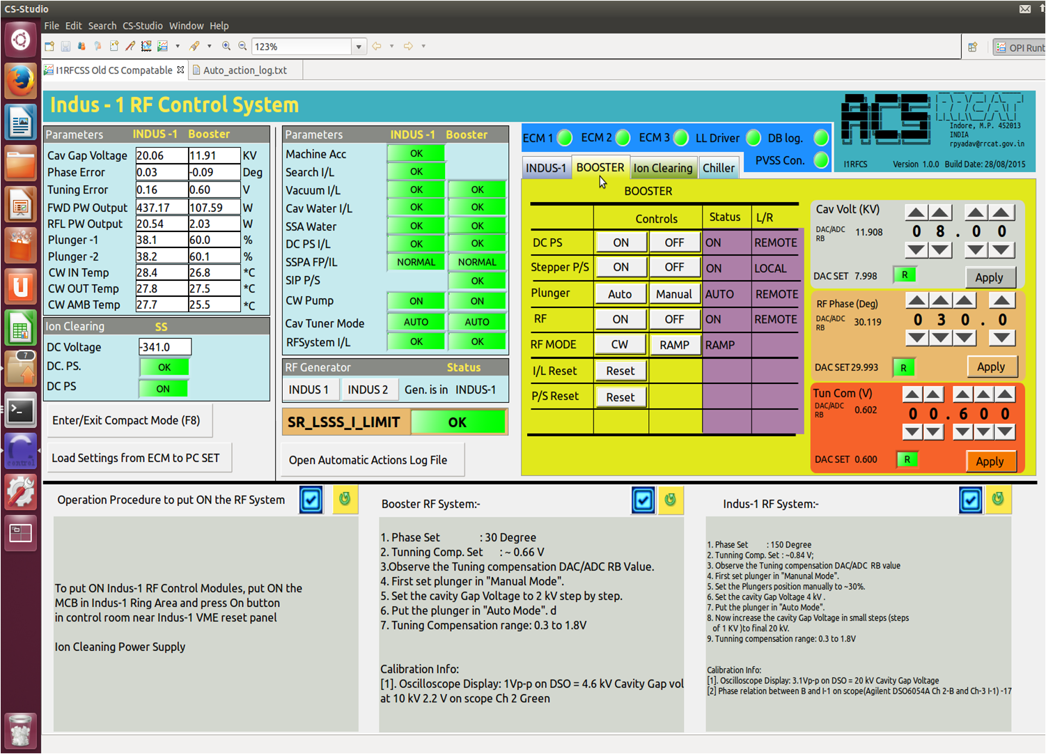
Fig.6:
Screenshot of Indus-1 RF control system Software GUI on Ubuntu20.04 LTS[Full Size Image] |
| |
|


