| Controls, Diagnostics and Beamline Instrumentation Division |
| |
| Architecture of Indus-1 SRS Control System |
|
|
| Overview |
The control systems for the subsystems of Microtron, Booster Synchrotron and the Indus-1 storage ring have undergone upgradation. The design of the control system for the Indus-1 facility is based on a two-layered architecture, modular and distributed architecture. The control system has personal computers (PC) based operator consoles and a number of VME Equipment Controllers or standalone Equiment Control Modules (ECMs) connected over a network. Ethernet along with Ethernet - RS 485/ RS 232 protocols converters are used as needed for communication between the two layers.
The main task of control system is to facilitate monitoring supervision and control of parameters of the machine and various subsystems. The control system consists of a number of subsystems, which work closely together and are responsible for an individual subsystem of Indus-1 like vacuum, magnet power supplies, RF, Timing & synchronisation, radiation monitoring, beam diagnostics etc. |
| Architecture |
Indus-1 Control System follows a 2-layered architecture. The top layer or control room layer
(layer-1) consists of Windws/ Linux PCs used as operator consoles. SCADA servers, Database servers, file servers, web servers are important elements on this layer which are common to Indus-2 control system, all being on the common network called AccNet. Various instruments like frequency synthesizer, oscilloscopes etc. are also part of this layer. Most of the sub-system applications are on SCADA while some use LabVIEW.
Functional subdivision at this layer has resulted in having one PC for each subsystem, though it is not mandatory. Each sub-system PC is connected over serial links to the bottom layer, Equipment Controller Station (ECS) or Equipment Control Modules (ECMs). ECMs for Magnet Power Supplies are named Power Supply Control Modules (PSCMs).
|
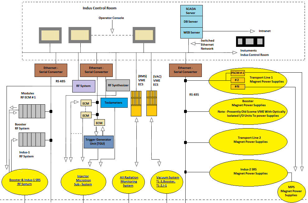
Figure: Indus-1 Architecture
|
|


