| Controls, Diagnostics and Beamline Instrumentation Division |
| Magnet Power Supplies Control System for Transfer Line-1 (TL-1), Transfer Line-2 (TL-2), Indus-1 Storage Ring (Indus-1 SRS) |
|
Indus-1 accelerator complex houses various accelerators viz, Microtron, Booster Synchrotron (BR), Indus-1 Synchrotron Radiation Source (Indus-1 SRS) also termed as Indus-1 storage ring and beam Transfer lines namely Transfer Line-1 (TL-1) and Transfer Line-2 (TL-2). Microtron is an injector and can be independently operated with a dedicated control system. Various magnetic components on the accelerators other than Microtron and that on transfer lines are excited in a controlled manner by more than 100 current controlled power supplies of different types and ratings. These power supplies are controlled from remote supervisory control systems. From controls perspective and operation wise, these accelerators and transfer lines are seen as four different sectors which are independently operated. Hence the control systems of the power supplies for magnets of these sectors are also put in four different sectors namely TL-1, BR, TL-2 and Indus-1 SRS. A dedicated supervisory control system monitors and controls power supplies of each sector. They also facilitate the operator for optimizing the beam parameters by changing the power supply parameters in a definite fashion.
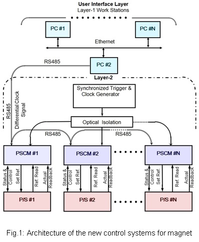
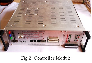
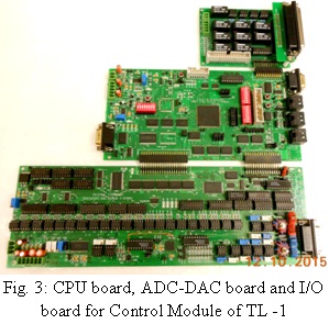
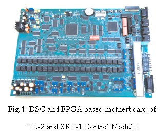
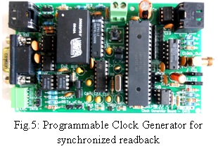
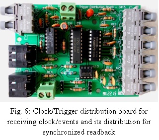
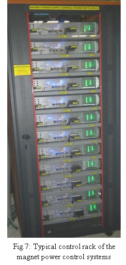
New control systems are developed for TL-1, TL-2 and Storage Ring of Indus-1 accelerator. The control systems are based on distributed control architecture (Fig.1) and cater to more than 1500 I/Os. Each of the magnet power supplies of TL-1, TL-2 and Indus-1 sectors is controlled and monitored by a dedicated controller module (Fig.2) on the front end. The controller module for TL-1 sector is based on Digital Signal Controller (DSC) (Fig.3) and controller modules for TL-2 sector and I-1 SR sector are based on DSC and FPGA (Fig.4). The controller module communicates with the user interface layer through a custom protocol and command set over RS-485 link. Embedded software modules are developed for the front end data acquisition, control and supervisory functions of the controller modules. The control module features the generation of current reference of any programmed shape particularly required for cycling profile, ramping profile etc and incorporate some features like synchronized data reading and fast data capturing which are useful for the analysis of transient phases of ramping and cycling. A separate layer of hardware is also implemented for generating clock for synchronized reading and its distribution. Fig. 5 shows programmable clock generator and driver module. At each hardware rack the clock is received by the receiver modules (Fig.6) and fed to various controller modules in the rack on fiber optic links. Fig.7 shows a control system rack housing multiple controllers.
|
 |
 |
|
[Full Size Image] |
[Full Size Image] |
| |
 |
 |
|
[Full Size Image] |
[Full Size Image] |
| |
 |
 |
|
[Full Size Image] |
[Full Size Image] |
| |
 |
 |
|
[Full Size Image] |
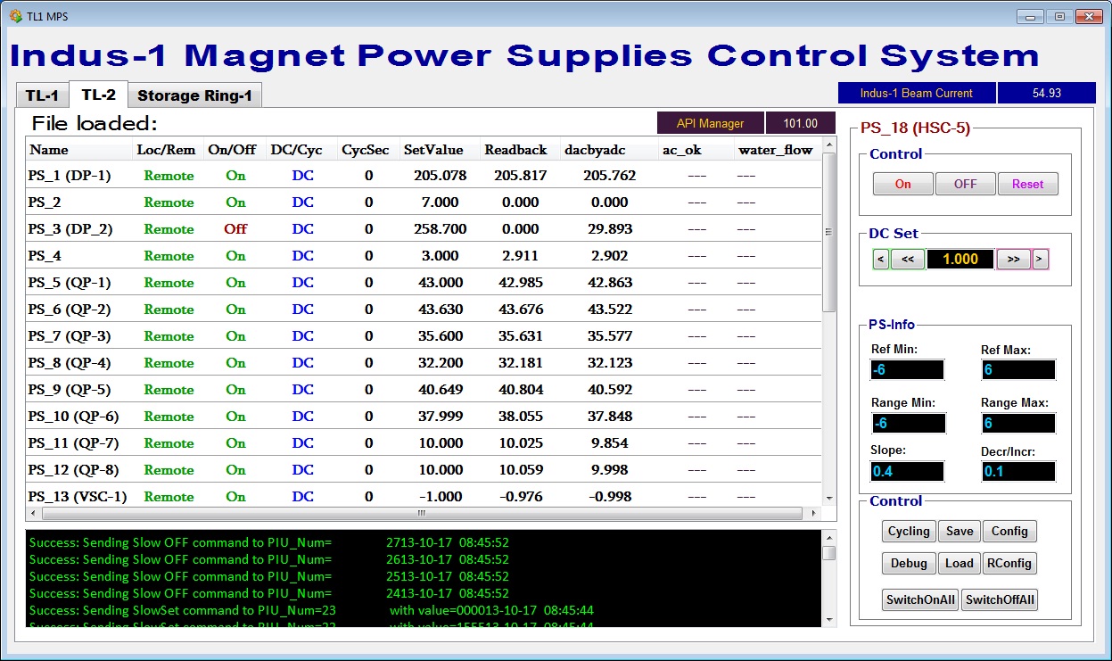
Fig.8: GUI (Operators Panel) [Full Size Image] |
| |
| API & GUI |
|
Application Program Interface (API) and Graphical User Interface GUI (Fig.8) are developed in SCADA. The API manager provides communication error logs, command logs, live list of control modules and configuration file based communication port parameters. The GUI software provides file loading, file saving and authentication based device configuration for slope, maximum operating range and cycling parameters. Power supply trip alarms are also configured. Data of the power supply settings, read-back and status etc. are logged in the accelerator database. Web applications are developed which facilitate query, retrieval, visualization and downloading of the logged data through the Web browser.
|
|


