Accelerator Controls & Beam Diagnostics Division
LCW Control System

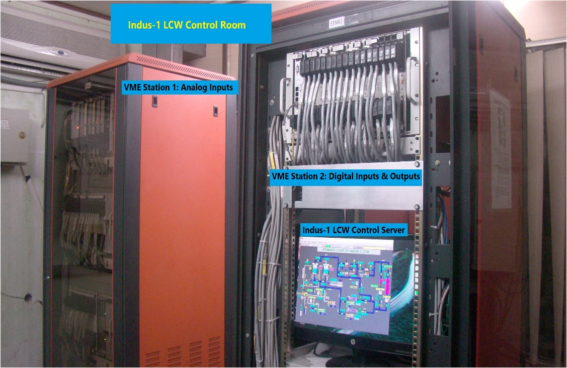
A picture of the racks containing VME DAQ stations VME L2 and L3 stations placed in the LCW plant control room area is attached below for Indus-1 and Indus-2 LCW system:

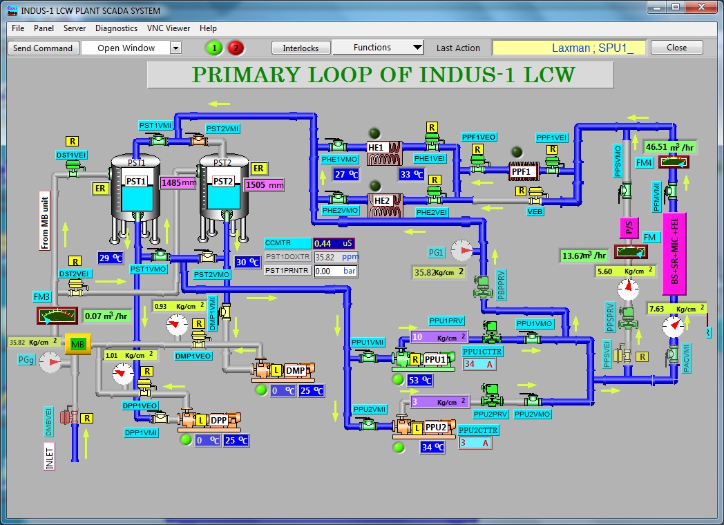
Snap of Indus-1 LCW Control Room with two VME stations and Control Server GUI of Indus-1 LCW Control System
Fig.1: Snap of Indus-1 LCW Control Room with two VME stations and Control Server [Full Size Image] Fig.2: GUI of Indus-1 LCW Control System [Full Size Image]
 

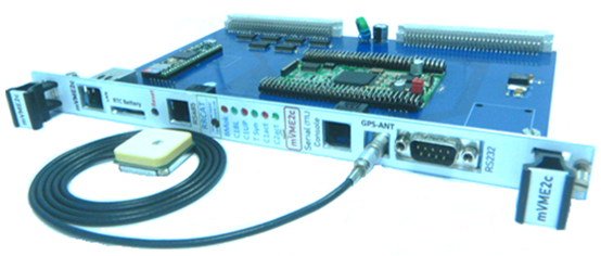
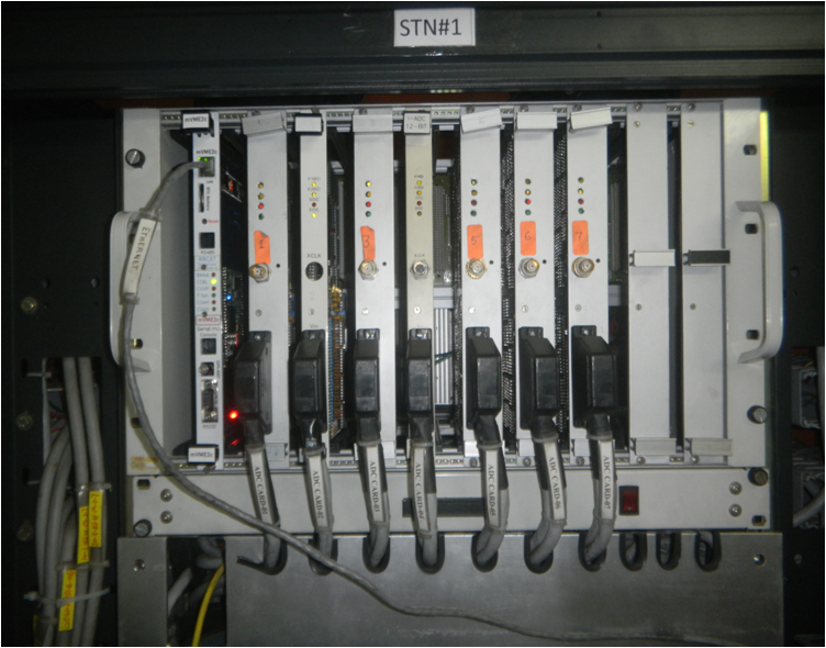
The Indus-1 LCW VME CPU used for DAQ of analog IO is updated to newly developed ARM based VME CPU board with enhanced VME feature like DTB32 and RTOS support with enhanced hardware capabilities. More details on the VME CPU development and specifications can be found in the development section of the ACSD pages. A snap of the newly developed CPU and VME station containing CPU is given below:

 
mVME2c board photograph mVME2c board in field testing
Fig.1: mVME2c board photograph [Full Size Image] Fig.2: mVME2c board in field testing[Full Size Image]
Best viewed in 1024x768 resolution