Physics Design of H- accelerator for the proposed Indian Facility for Spallation Research (IFSR) and other applications:
India has a long term nuclear program for Accelerator Driven Systems (ADS) that can utilize the much abundant thorium in the country for electricity generation to meet the ever growing energy demands. One of the challenges in developing ADS is the high (~10 MW or more) average power, high energy (~1 GeV) proton accelerator. Such an accelerator has not been demonstrated anywhere in the world so far. On the path towards ADS, there is a proposal to develop an Indian Facility for Spallation Research (IFSR) at RRACT that will require a 1 GeV, 1 MW average power proton accelerator. Such accelerators have been developed only during the last two decades in some laboratories around the world. The main advantage of a spallation neutron source compared to a reactor based neutron source is that it can produce short (~100 μs) pulses of neutrons with very high peak flux (~10
16 cm
-2 s
-1) for the time of flight experiments. With the added advantage of operational safety and non-proliferation issues compared to nuclear reactors, such an accelerator based source of spallation neutrons has become a very attractive choice in recent times as neutron source for experimental studies of condensed matter physics and materials research for energy applications and various engineering applications.
Primary parameters of the accelerator of IFSR are given in the following Table:
|
Proton beam power on target
|
1.0 MW
|
|
Proton beam kinetic energy on target
|
1.0 GeV
|
|
Average beam current on target
|
1.0 mA
|
|
Average linac macropulse current
|
10 mA
|
|
Linac beam macropulse duty factor
|
10%
|
|
Protons per pulse on target
|
1.25 × 10¹⁴
|
|
Proton pulse length on target
|
680 ns
|
|
Ion type (Front end, Linac, HEBT)
|
H-
|
|
Ion type (Ring, RTBT, Target)
|
proton
|
|
Ring filling time
|
2.0 ms
|
|
Ring revolution frequency
|
1.0 MHz
|
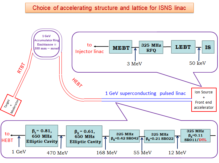
The accelerator physics study for evolving a suitable design of various subsystems of 1 GeV H
- Linac and proton Accumulator Ring (AR), along with associated transfer lines for the proposed 1 MW Indian Spallation Neutron Source is a major activity of the section. The schematic layout of the accelerator for IFSR, starting from the ion source to the "Ring to Target Beam Transport" (RTBT) line is shown in the figure given below.
|
Schematic layout of the accelerator for IFSR |
The physics design of Low Energy Beam Transport (LEBT) and 3 MeV RFQ has been completed and these systems are presently being built at RRCAT. Design of a 2 MeV proton RFQ, as an injector for 230 MeV medical synchrotron is also being explored. Numerical studies have been performed for field tuning of the RFQ structure in simulation environment. The electromagnetic design of different superconducting accelerating structures for the injector linac has been completed.A normal conducting Drift Tube Linac (DTL) to accelerate the 3 MeV H- beam to 12.6 MeV has also been designed, as a substitute for the superconducting SR011 section shown in the above figure. A general methodology for making a compact design of a 1 GeV, 1 MW H- linear accelerator has been developed and studies for obtaining a suitable lattice of this accelerator, including the effect of various errors and component failure is in advanced stage. Results of end to end beam dynamics simulation of the linac for a particular lattice are shown below:
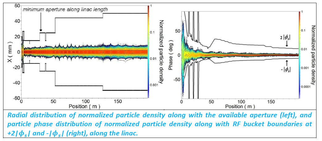
An important design requirement of the 1 GeV H
- injector linac is to ensure that the uncontrolled beam loss along the linac is < 1 W/m. Extensive Studies on beam loss due to intra-beam stripping and other mechanisms have been performed. Most significant contribution comes from intra-beam stripping, and results of calculation of beam loss due to intra-beam stripping is shown in the following figure
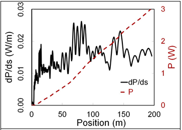
Power loss per unit length (black, solid line), along with integrated power loss (red, broken line) due to intra-beam stripping along the linac length.
In addition, detailed studies on beam instability and halo formation have also been performed.
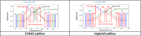
For the 1 GeV accumulator ring, two types of lattices – FODO and Hybrid have been designed and are being studied in detail from the point of view of dynamic aperture, beam collimation, beam injection, beam extraction and electron cloud formation.
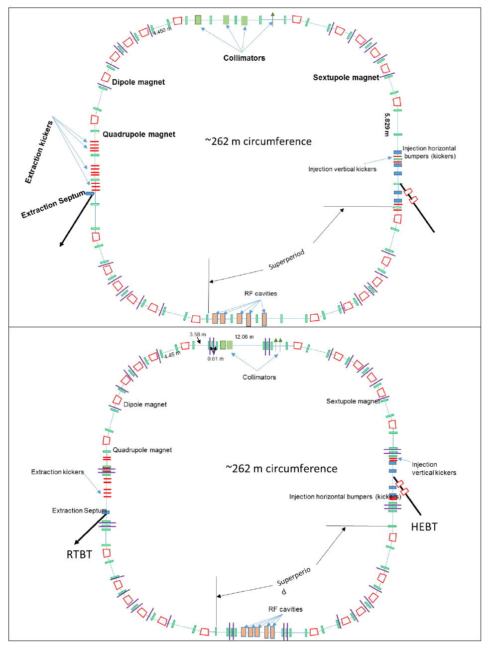
Schematic layout of FODO lattice (top) and Hybrid lattice (bottom) of 1 GeV accumulator ring
A suitable High Energy Beam Transport (HEBT) line to match the beam from the linac to the injection point of the accumulator ring has been designed. For injecting a long pulse (~ 2 ms) of H- in the accumulator ring, a beam injection system has been designed to perform the required phase space painting, using nearly 2000 turns charge exchange method. Layout of the beam injection scheme that has been evolved, is shown in the following figure.
Layout of the injection scheme for Accumulator Ring. Magnets in red and blue colour are horizontal and vertical injection magnets, respectively. Magnets in green colour are quadrupole magnets of the lattice.
Detailed studies are going on to optimize the design of Ring to Target Beam Transport (RTBT) line, taking the possibility of failure of two extraction kickers into account.
More recently, design studies have been initiated for the 2 MeV proton injector linac for the 70-250 MeV proton synchrotron for medical applications. Physics design studies have been performed for a 2 MeV proton RFQ based injector for injecting 24 mA beam with a relative momentum spread of 0.35% (FWHM) into the synchrotron.


 Accelerator and Beam Physics Section