 Home Laser Controls & Instrumentation Division
Machine Vision Systems
LCID is involved in development of machine vision based systems for Nuclear Fuel & various components used in assembly of nuclear fuel. LCID is developing these systems in collaboration with various other units of DAE which are :
- Nuclear Fuel Complex (NFC), Hyderabad,
- Atomic Minerals Division (AMD), BARC, Mumbai
- Atomic Fuel Fabrication Facility (AFFF), BARC, Tarapur
These inspection systems are broadly categories in three main types:
- Machine vision based metrology systems
- Machine vision based OCR/OCV systems
- Machine vision based inspection systems
Machine Vision based Metrology Systems
- System to measure dimensions of slot present on Top plug of FBTR fuel pin
- Dimensional Inspection System for PHWR Fuel Punches
- Bearing Pad Dimensional Inspection System
- Metrology System for BWR Plugs
- Machine vision based inspection system for inspection of chamfer on clad tube
- PHWR Fuel Element (37e) End Profile Inspection System
- End plate dimension measurement system
- End plug dimensional inspection system
- Metrology System for Industrial Components
- High throughput machine vision based metrology system for end caps
Machine Vision based OCR/OCV Systems
- PHWR Fuel Bundle Number Identification System
Machine Vision based Inspection Systems
- Pellet Inspection System
- FBTR weld metallograph inspection system
- PHWR Fuel Tubes Inspection System
Machine Vision based Metrology Systems
Industrial production houses such as nuclear, automotive, aerospace, defence, etc. impose very stringent dimensional tolerances for critical components and systems. This imposes extreme challenges during fabrication, assembly and final product qualification too. Complex systems usually involve hundreds of different components of various sizes and complex geometries which demand precise component dimensions. Machine vision plays a pivotal role in inspection of components, their assemblies due to very high measurement resolution (down to few microns). Machine vision based measurements are non-contact hence remote inspection is possible. Automated inspection of components with high throughput can be easily achieved with this method.
LCID, RRCAT has developed expertise in machine vision based metrology systems for dimensional inspection. These systems have been specially designed and developed as per the custom needs to maximize the inspection throughput and fulfil the accuracy and repeatability requirements of the user. These systems are based on shadow graph technique. These systems are provided with suitable component holder/jig. The software developed provides component accept / reject decision along with complete report of all the measurements carried out for the component.
The metrology system mainly consists of two sections viz., illumination optics (on one side of component under measurement) and imaging optics (On other side of component under measurement). The component whose dimensions are to be measured, is kept between these two sections (usually component holder or glass plate is used). Illumination optics generates shadow of component under test which is captured by imaging optic. The system has in built embedded processor. Image processing & measurement software running on this processor measures different dimensions of component under test with customized report for the user. The dimensions are measured by sampling the specimen at many locations and typically min, max and average values of the dimension are reported. Industrial components have variety of sizes. Depending on component measurement requirements and accuracy differ widely. Thus we have developed customized solutions keeping in mind the size of the component and accuracy and repeatability requirements.
Following metrology systems for end plate, end plug and various test specimens have been developed.
System to measure dimensions of slot present on Top plug of FBTR fuel pin
Figure b shows photograph of top plug of FBTR fuel pin. Dimensions of the slot on this top plug is is very critical. LCID has developed LED pattern projector based metrology system to measure slot width, slot depth & slot angle present on the top plug. This is a standalone system with embedded controller and with LCD touch screen display for human machine interface (HMI).
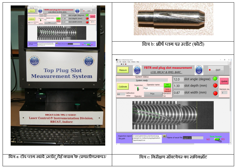
Fig. a: Top plug slot measurement system Fig. c: Screenshot of inspection software
As shown in figure c a stripe pattern (alternate black & white stripes) is projected on the top plug. The slot on top plug modifies the light pattern. Modification in stripe pattern is acquired by camera and this image (of modified stripe pattern) is processed by embedded controllers to measure slot width, slot depth & slot angle. Software then accept or reject the plug based on the acceptance criteria provided by user. Compared to manual inspection, this system is faster, accurate and reduces human fatigue. Specification of the developed system are as follows:
| Depth resolution | 8 µm |
| Repeatability | 10 µm (approx) for slot depth and width, 0.2 ° for slot angle |
| Throughput | 2 seconds/plug |
| Inspection report | saved automatically |
This system is operational at Radio Metallurgy Division, BARC
Dimensional Inspection System for PHWR Fuel Punches
| Field of view | : | 31 mm x 31 mm |
| Resolution | : | 6 µm(Back Light), 7 µm (Front Illumination) |
| Repeatability | : | < 5 microns |
| Accuracy | : | ± 5 micron |
| Throughput | : | 20 punches / hour |
This machine vision system consists of two Imaging systems:
i) Based on Structured front illumination: for profile of tip of punch
ii) Based on Back illumination : for outer dimensions of Punch
A magnetic holding zig has been designed & developed for all 6 variants of punches (varying in length 30 mm to 110 mm and have different diameters) which ensure repeatable and easy placement. To cover entire length of punch, punches are scanned using high precision linear translation stage. System measures all dimensions of punches on a single click. System has three times higher throughput as compare to manual inspection.
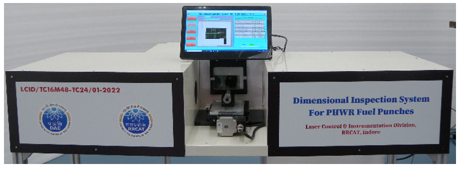
Photograph of Dimensional Inspection System for PHWR fuel punches
Bearing Pad Dimensional Inspection System
Machine vision based automated dimensional inspection system is developed for 8 variants of bearing pads of PHWR fuel elements. System has two imaging setups which captures side view and top view image of bearing pad simultaneously. System measures typically 11 dimensions (as per drawing) of different bearing pads. Single user friendly GUI for measurement of all the variants of bearing pads.
Specifications:
| Field of view | : | 35 mm X 29 mm |
| Resolution | : | ~ 15 microns |
| Repeatability | : | 10 microns |
| Accuracy | : | ± 10 microns |
| Throughput | : | 3 samples / min |

Metrology System for BWR Plugs
Specifications:
| Field of view | : | 70 mm x 55 mm |
| Resolution | : | ~ 15 microns |
| Repeatability | : | < 10 microns |
| Accuracy | : | ± 15 microns |
| Throughput | : | 3 plugs / minute |
Machine vision based automated metrology system based on non-contact shadow graph technique is developed for dimensional measurement of 10 variants of BWR plugs with complex shape and geometry. System measures typically 10-15 dimensions (as per drawing) of different plugs on a single click using user friendly measurement software. 100% inspection is possible using this system.
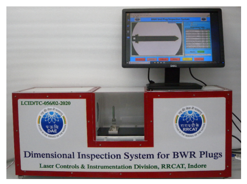
Photograph of Metrology System for BWR Plugs
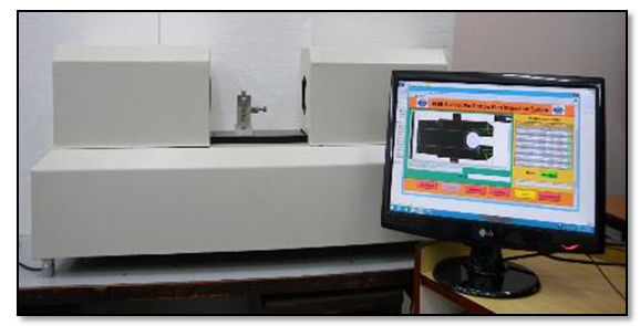
Machine vision based inspection system for inspection of chamfer on clad tube
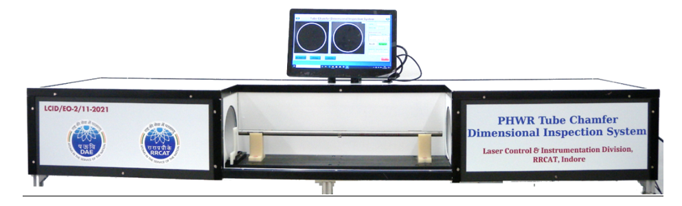
Photograph of Tube Chamfer Dimensional Inspection System
Specifications:
| Field of view | : | 25.6 mm x 19.2 mm |
| Resolution | : | 6.27 µm |
| Repeatability | : | < ± 7 micron |
| Accuracy | : | < 7 micron |
| Throughput | : | 240 tubes / hour |
| Measurement Operation | : | Using foot Switch, Touch Panel, Keyboard, Mouse |
A machine vision based automated dimensional inspection system based on dark field, front light illumination technique has been designed and developed. System simultaneously measure of V-shaped end chamfer of both ends of clad tube of 19-e and 37-e fuel assembly of PHWR reactors in a single shot. Inspection system has throughput of 240 tubes / hour which is 4 to 5 times higher compare to manual inspection and unlocks the path for 100% inspection. It is also observed that from images chamfer damage can be clearly visible. Automated chamfer damage detection is possible.
PHWR Fuel Element (37e) End Profile Inspection System
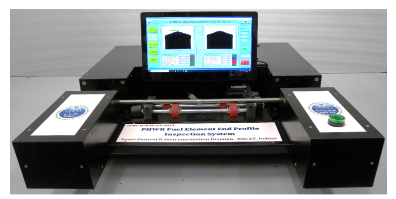
Photograph of Element End Profile Inspection System
Automated Machine vision system consists of two Imaging setups based on shadow graph to inspection both ends simultaneously. To cover entire circumference of end, element is rotated 180 degree and
180 images of each end are acquired and processed at every 1 degree. System measures 9 parameters of end profile with resolution of 10 micron. System has throughput of 200 Elements/ hour which makes 100 % Inspection possible.
End plate dimension measurement system
Specifications:
- Field of view : 100 mm x 94 mm
- Resolution : 30 microns
- Repeatability : 15 microns
- Throughput : 3 plates/ minute
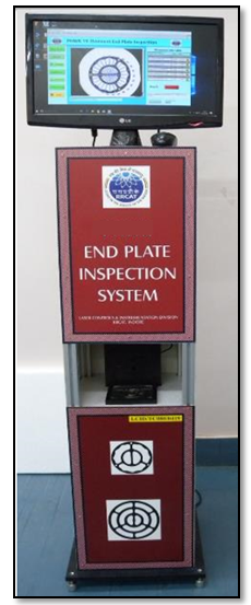
Photograph End Plate Inspection System
The outer diameter of end plate is a critical parameter. Hence it is measured at 100 different locations. Using these 100 readings average diameter of the end plate is calculated and displayed to the user. Apart from this, software reports maximum and minimum diameter as well. On basis of these measurements accept / reject criteria can be set by user. Software also provides calibration procedure to calibrate the instrument.
End plug dimensional inspection system
Specifications:
- Field of view : 46mm x 38mm
- Resolution : 20 microns
- Repeatability : 20 microns
- Accuracy : ±20 micron
- Throughput : 4 plugs/ minute
Photograph of end plug Inspection System
Metrology System for Industrial Components
This system measures the dimensions of different industrial test specimens of varying geometry and size for studying different mechanical properties of the specimen under test. The system has embedded processor running customized image processing & measurement software for measurement of different dimensions of specimen under test with customized report for the user.
Specifications:
- Field of view : 60 mm x 45 mm
- Resolution : 13 microns
- Repeatability : 10 microns
- Accuracy : ±13 microns
- Throughput : 3 Specimens / minute

Shadowgraphs of different test specimens
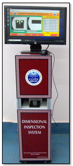
Photograph of Metrology System for Industrial Components
These systems can work in semi-automatic mode with operator feeding the components or can be easily integrated with the pick & place, SCARA robot or any other suitable multi axis robotic manipulator to automate the entire inspection task. The machine vision based systems use commercially off the shelf industrial components, and thus suitable for inspecting any industrial component or system. The knowledge base and expertise developed over the years at LCID can be leveraged for developing inspection system of any other component as well.
Machine Vision based OCR/OCV Systems
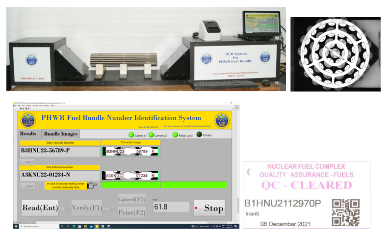
PHWR Fuel Bundle Number Identification System
A machine vision based OCR system is developed to read fuel bundle number of 37 element PHWR fuel bundle. It is a standalone system consisting of 2 imaging setups, 1 embedded controller, printer and touch screen monitor. Each fuel bundle has a unique number assigned to it, which is based on various parameters and used throughout life cycle of the bundle. This system reads fuel bundle number from both ends of bundle. It consists of 5M pixel camera-lens system and dome light illumination which capture images with FOV of 100 mm X 100 mm. The software processes the image and recognizes bundle number inscribed on bundle. Presence of uneven gray background in image makes it challenging to read and reconstruct the number. Bundle number is identified from images, irrespective of orientation (0 to 360 degree) and position of bundle. Numbers are checked for their correctness and equivalent QR code is generated for tagging the bundle.
Machine Vision based Inspection Systems
Pellet Inspection System
A computerized Machine Vision Based Inspection System is developed in order to perform visual surface inspection of cylindrical fuel pellets.
This inspection system includes an imaging system that gives a high quality unfolded image of the pellet surface. The imaging system includes a high resolution camera, machine vision lens and custom designed illumination. To process the obtained image, image processing software is developed for automatic detection of defects on the pellet surface, its quantification and analysis.
Machine Vision Based Inspection System
The system generates a throughput of 2.5 second/pellet. Among the pellets accepted by the system, correct decision was made in 98.3 % of the pellets. Among the pellets rejected by the system, correct decision was made in 85 % of the pellets.
The system is advantageous over human eye due to its reliability, high speed and accuracy, ability to quantify defects for qualitative assessment.
FBTR weld metallograph inspection system
Metallography is study of the physical structure & components of metals using microscopy. To study quality of weld between top plug and fuel pin metallography technique is used by RMD. LCID has developed weld metallograph inspection system which consist of two different imaging systems. The first imaging system has magnification 0.35x with ring light illumination, whereas other imaging system has 6X magnification with coaxial illumination. Two different illumination are chosen to enhance the image quality of metallograph.
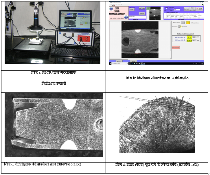
Lower magnification image is used to measure depth of weld pool, length of weld pool, wall thickness of tube near weld, distance of weld pool from end of plug. While the higher magnification image of weld pool is to inspect quality of weld & grain structure in weld area. White semicircle in Figure C shows the weld pool, where as fig d shows the grain structure in weld pool.
Both these imaging system have a common controller with embedded processor. The software running on embedded controller has facility to choose the imaging system. Inspection software processes the images obtained from these two imaging systems. In case of image obtained from imaging system with 0.35X magnification, software performs measurement such as weld pool penetration at junction, maximum penetration of weld pool, shift of maximum penetration from the junction, weld pool width and tube thickness.
With 6x system, software indicates probable region/area where microstructure defects like porosity, inclusion, cracks, lack of penetration, undercut. It is left to user to confirm presence of these defects. To automate the process of identification of defects, AI algorithms are required and LCID is planning to develop them with help of RMD
Specifications of Imaging system :
1. Optical resolution of system with 0.35x magnification = 2.2 µm/0.35 ≈ 7 µm
2. Optical resolution of system with 6x magnification = 2.2 µm/6 ≈ 0.4 µm
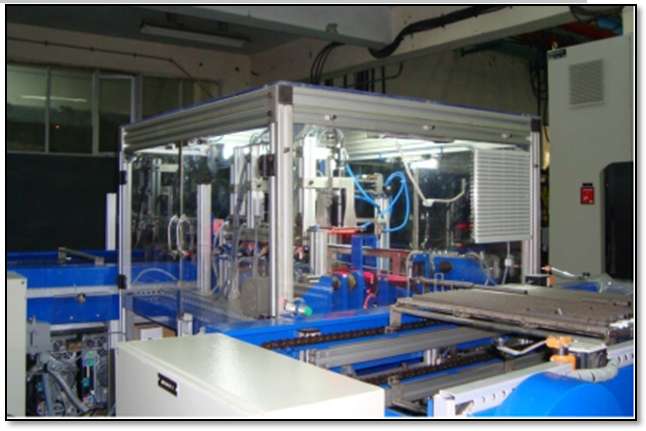
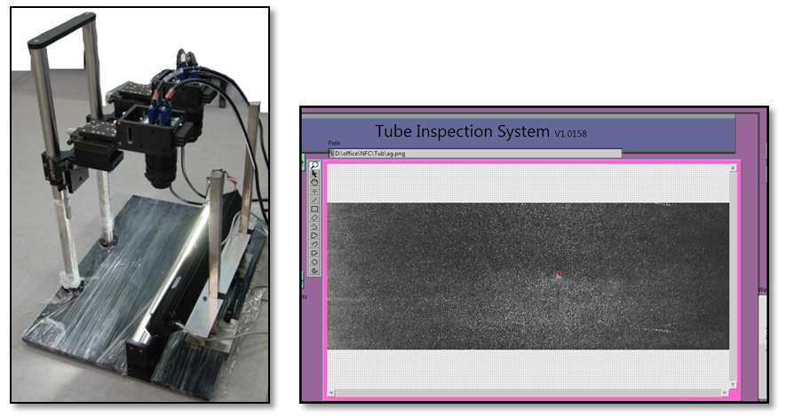
PHWR Fuel Tubes Inspection System
Machine vision based inspection system to detect surface defects on PHWR fuel tube is developed for NFC, Hyderabad. NFC has defined defects categorised as dents, pits, handling defects, tool mark, flattening, burning chattering and handling defects. The system comprises of 2 no. 8K line scan cameras and 2 no. 12” line lights to image full 500mm length of the tube. The tube is rotated on a rotating mechanism. Software is developed and deployed on PC to analyze the defects on the tube.
|


