|
Time resolved x ray diffraction studies
Introduction:
Time Resolved x-ray diffraction (TXRD) is a method to detect fast phenomena occurring inside crystals. It is a pump probe method which uses ultra-short x-ray pulse as probe and with ultra-short laser pulse as optical pump. Optical pump-probe is often utilized to detect various fast phenomena happening inside materials but it can give information about only surface hence it is termed as indirect method. On the other hand, x-ray diffraction is widely used for crystal structure determination and hence TXRD can be used to detect crystal dynamics in real time.
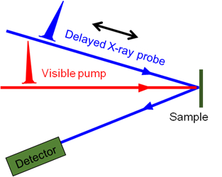
Figure 1: Schematic of time resolved x-ray diffraction (TXRD)
Ultra-short x-ray source:
Usual x-ray sources such as x-ray tubes, synchrotrons have large pulse duration (~ ns) hence they have limited applicability in TXRD studies. Large facilities such as x-ray lasers are very expensive and huge facility and hence not very common. In this regard, laser plasma based Kα x-ray source have unique property of having ultra-short duration (~100 fs), fairly small line width (λ/Δ λ ~103), and small facility.
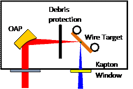
Figure 2: Generation of ultra-short x-ray source
To generate Cu Kα x-rays a laser having energy of ~6 mJ, pulse duration ~50 fs (FWHM) operating at 1 kHz repetition rate was used. The experimental setup is shown in Figure 2. The laser beam was focused using f/8 off-axis parabolic (OAP) mirror on a moving Cu wire target of 300 μm diameter. A clear moving plastic tape was placed between OAP and wire target assembly to protect the OAP from plasma debris. The Kα photon flux was detected by CdTe detector and it is measured to be >1×10¹⁰ photons sr−1 s−1. Figure 3 shows a typical x-ray spectra recorded by CdTe detector.
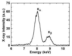
Figure 3: x-ray spectrum detected by CdTe detector
Kα generation from ultra-short laser solid interaction:
Interaction of intense ultra-short laser with solid generates hot electrons. These hot electrons when interact with cold solid generates Kα radiation. The duration of hot electrons is similar to laser pulse duration. These hot electrons penetrate in cold solid and are able to generate the Kα radiation as they propagate deeper. Due to this the duration of Kα radiation is slightly higher than the laser pulse duration.
Time resolved x-ray diffraction in semiconductor crystals:
Photograph of TXRD setup is shown in Figure 4. Ultra-short x-rays are taken out from kapton window and allowed to diffract from sample (InSb (111)). The sample was pumped by an optical pump (Ti:sapphire laser pulse) before the arrival of x-ray probe. The change is the diffraction pattern is recorded by an x-ray CCD camera.
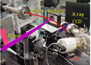
Figure 4: Photograph of TXRD experiment. X-ray probe is depicted by red line and pump laser is depicted by purple line.
Results:
Lattice expansion via laser irradiation
A typical x-ray diffraction pattern after laser excitation is shown in Figure 5. The InSb(111) crystal was irradiated by a fs laser (wavelength = 800 nm) at a fluence of 13 mJ/cm2. The x-ray diffraction from the pumped region is distinctly different from the pristine region. The line profile of the two regions revealed that the x-ray diffraction from the pumped region shifts towards lower angle side, which signifies lattice expansion.
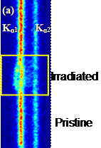 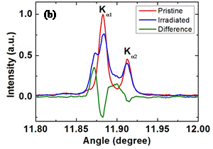
Figure 5: (a) x-ray diffraction image from InSb (111) sample at 80 ps after laser pump. 5(b) lineout of the pristine (red) and irradiated (blue) parts. Green curve shows the difference between two. The shift towards lower angle side signifies lattice expansion.
Two temperature model
Excitation of sample by the fs laser pulses causes transfer of electrons from valance band (VB) to conduction band (CB) by single photon absorption process. These electrons are thermalized in CB within ~100 fs time scale. Within few ps these electrons start transferring their energy to lattice resulting in heating and expansion of the lattice (Figure 6). The strain generated due to crystal heating is propagated inside the crystal via electron diffusion. Initially the strain is large but confined, with time the strain start propagating inside the crystal and decreases gradually.
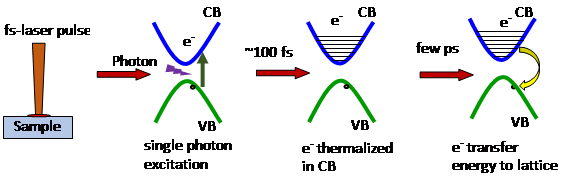
Figure 6: Schematic of crystal heating after laser excitation.
The strain propagation inside the crystal is simulated by assuming two temperature model. The model adequately reproduced the observed experimental results. Figure 7 shows the comparison of experimentally observed and simulated lattice strain temporal evolution in the crystal. 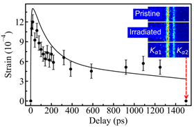
Figure 7: Experimentally observed and simulated strain in the crystal.
Estimation of strain propagation velocity
Experimentally observed x-ray diffraction profile from InSb sample at 80 ps after laser excitation is shown in Figure 8 (a). It may be noted here that the x-ray diffraction due to strained sample is appeared at an angle lower compared to original Bragg angle however the intensity of x-ray diffraction at original Bragg angle is decreased. The decrease in the x-ray diffraction intensity by the pristine sample is attributed to the absorption of x-rays during its travel to the pristine sample through strained crystal. The magnitude of absorption depends on the thickness of strained sample. This simple fact is then utilized to calculate the strain propagation velocity inside the crystal. Calculated strain propagation depth and strain propagation velocity is shown in figure 8 (b).
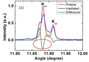 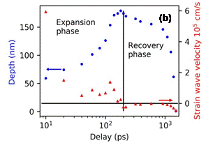
Figure 8: (a) Experimentally observed x-ray diffraction profile from InSb(111) sample at 80ps probe delay. (b) calculated strain propagation depth and velocity from the dip in x-ray reflectivity at original Bragg angle.
For more detail please see the publications appearing on the website.
|


