| FEL & Utilization Section |
 FEL & Utilization Section
Development, upgrade and regular operation of the Infra-red Free Electron Laser (IR-FEL).
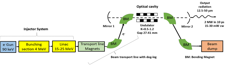
An Infra-Red Free Electron Laser (IR-FEL) designed to lase in the 12.5 - 50 μm wavelength band has been built and commissioned at RRCAT, Indore. A schematic of the IR-FEL is shown below in Fig.1, and Fig. 2 shows a picture of the IR-FEL installed inside a 60 m [L] x 5 m [W] radiation shielded vault.
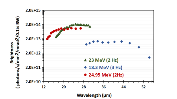
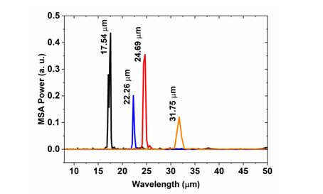
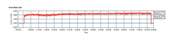
Wavelength tunability of the IR-FEL radiation from 12.5 - 50 µm has been achieved, with a peak out-coupled power > 7 MW and CW average out-coupled power > 25 mW at 21.8 µm wavelength at 2 Hz pulse repetition rate. This translates to a peak Spectral Brightness ~ 1018 photons/s/mm2/mrad2/0.1% BW and Continuous Wave (CW) average Spectral Brightness ~ 2 x 10¹⁴ photons/s/mm2/mrad2/0.1% BW at source. The typical measured spectral width of the IR-FEL radiation is ~1.4 % at 22.7 µm wavelength. The IR-FEL light is monochromatic and continuously tunable over its design wavelength range. Figure 3 below shows the IR-FEL wavelength tuning curve, and Fig. 4 below shows the measured IR-FEL radiation spectra at different wavelengths. The IR-FEL setup is qualified through experiments to deliver >80 mW CW average out-coupled power with operation at a higher duty cycle. The typical power stability of the out-coupled IR-FEL radiation is shown in Fig. 5 below.
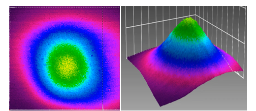
With regulatory consent from the Atomic Energy Regulatory Board (AERB), India, infra-red light from the IR-FEL is regularly delivered at the user stations with a maximum measured micro-pulse energy > 35 µJ and a CW average power > 7 mW at 17.7 µm wavelength. A dry Nitrogen flushed optical beam transport line is employed to transport the IR radiation from the IR-FEL inside the radiation shielded vault to the user station over a distance >55 m. This optical beam transport line uses 21 gold coated copper mirrors and beam matching stations at both ends for efficient transport of FEL radiation to the user stations. Typical 2D and 3D transverse optical mode profile of the FEL radiation, measured at a user station by employing a Pyrocam beam profiler [Make: Ophir Spiricon, Model: Pyrocam IV], is shown in Fig. 6 below.
Table 1 below summarizes the IR-FEL and the electron beam parameters. More details about the user facilities are given in the next section.
|
Figure 1: Schematic of the IR- FEL at RRCAT Indore, India. |
|
Figure 2: The IR-FEL setup installed inside radiation shielded area [60 m x 5 m x 3.5 m (L x W x H)] |
|
Figure 3: Wavelength tunability curve of the IR-FEL for various electron beam energies. The PRR during the operation is given in brackets next to the beam energy. |
|
Figure 4: Typical IR-FEL wavelength spectra measured at the user laboratory using a Michelson interferometer with a resolution of 5 cm-1. Each coloured line represents a spectrum obtained for a particular undulator gap for a particular electron beam energy. |
|
Figure 5: Typical stability of sampled CW average IR-FEL power, with a measured σ ~ 0.18 mW and Mean ~ 4.45 mW over a 6 hour period from 12:30 PM. The IR-FEL operation wavelength is 20 µm. |
|
Figure 6: Typical 2D (Left) and 3D (Right) transverse optical pulse profile measured at an experimental beam port, using a Pyrocam |
Table 1: Typical parameters of the IR-FEL |
| Spectral range | 12.5 - 50 μm
24 - 6 THz
200 - 800 cm-1
|
| Typical measured spectral width | 1.4% at 22.7 µm |
| Pulse structure and power: |
| Micro-pulse Repetition Rate | 29.75 MHz or 59.5 MHz |
| Micro-pulse width (FWHM) | ~10 ps |
| Macro-Pulse Repetition Rate | 1- 4 Hz |
| Macro-pulse width with saturated lasing | 4 - 6 μs |
| Typical out-coupled CW average power at source | > 25 mW at 21.8 µm @ 2 Hz with 29.75 MHz micro-pulse repetition rate |
| > 80 mW at 21.8 µm at 4 Hz with 59.5 MHz micro-pulse repetition rate |
| Maximum out-coupled peak power at source | > 7 MW at 21.8 μm wavelength |
| Typical IR power transmission to user area over a distance ~ 55 m | > 30% with an optical beam transport line comprising 21 mirrors and two matching stations |
| Other parameters: |
| Electron beam energy | 18 - 25 MeV |
| Undulator period / Number of periods | 50 mm / 50 |
| RMS Undulator Parameter | 0.5 -1.2 |
| Optical cavity length | 5.04 m |
|
|
|
|


![Figure 2: The IR-FEL setup installed inside radiation shielded area [60 m x 5 m x 3.5 m (L x W x H)]](images/fel_pic_3.PNG)