Introduction
Infrared (IR) spectroscopy provides information about the nature of chemical elements in molecules/materials, chemical groupings etc. IR spectroscopy is very useful in the analysis of organic, semiconductors and biological systems for their identification, detection of low level impurities such as oxygen/carbon in ultra high pure materials and various kinds of transformations brought about by extreme thermodynamic conditions like high pressure and high/low temperature. Another application area is the electronic investigations of metallic samples viz. reflectivity, interband/intraband transitions, metal to insulator transition; optical properties like refractive index, dielectric constant and optical conductivity in the infrared region.
With the use of interferometers, no dispersive element is required in the infrared beamline and hence complete spectral range can be measured in a single scan with the use of various sources, including internal sources as well as synchrotron source for samples of the order of tens of microns, in different parts of the electromagnetic spectrum, i.e. far, mid and near IR regions. The use of infrared part of the synchrotron radiation (SR) source, owing to its brilliance advantage, can be exploited in a range of spectroscopic studies in the fields of material science to biology, medicine, geology, environment and cultural heritage.
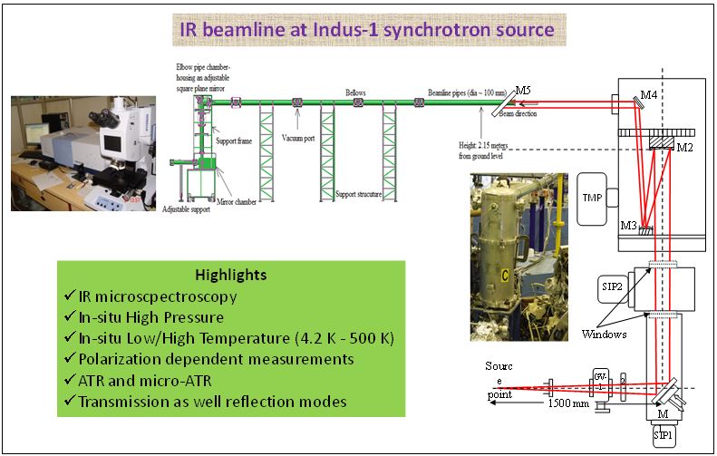
The infrared beamline has been set up at the bending magnet port of the Indus-1 synchrotron radiation source. The acceptance angle at Indus-1 assured the use of the infrared part of the synchrotron source to cover the vital ‘fingerprint’ region and the complete range from ~ 600 cm-1 (0.72 eV, 17.2 µm) to ~ 8000 cm-1 (1 eV, 1.2 µm). Indus-1, a low energy synchrotron source with electron energy of 0.45 GeV, is devoid of high energy hard x-rays and offers easier accessibility to the front end and low heat load on optical components. The SR beam is collected from the 10° port of the bending magnet. All the beam manipulation using optics is carried out in the vertical plane. A pair of spherical mirrors has been used to collimate the beam employing a focusing-defocusing geometry. The collimated beam is 180° back folded and sent towards the experimental station. A pair of ZnSe windows is used to isolate the storage ring UHV and the rough vacuum in the rest of the beamline and the spectrometer. With ZnSe windows, it is also possible to use the radiation in the near infrared region, which is advantageous in experiments like metallic reflectivity measurements in broad spectral regions in order to estimate the optical properties and carrier density. Near the experimental station, the beam manipulation is carried out using two gold coated parabolloidal mirrors of different focal lengths to couple the beamline with the FTIR spectrometer.
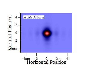
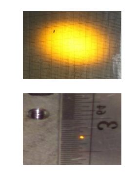
The beamline is primarily designed for infrared microscopy experiments in the mid and near infrared regions using diamond anvils and a focused beam of 10 – 100 µm spot size at the sample in the first stage. This beamline is currently being used for in-situ high pressure IR spectroscopy of materials under extreme thermodynamic conditions and shall be developed into a versatile facility for IR microscopy investigations in a wide range of physical, chemical, biological and geological fields. The present broad optical windows used in the beamline are coated for enhancing the transmittance of the window material. But, it also leads to interference effects leading to dips in some spectral regions. New broad band coated windows, mounted on appropriate UHV flanges, currently under fabrication, are expected to facilitate more than 90% transmittance in the complete range. Apart from infrared microscopy, other experiments like polarization dependent measurements, ATR and in-situ low temperature infrared spectroscopic studies are also possible at this facility. The cryogenic system has been installed and tested using both liquid helium as well as liquid nitrogen, which allows the studies up to temperatures as low as 4.2 K.
Specifications:
Instrument: |
Bruker Vertex 80V (10 – 12000 cm-1) with maximum resolution ~ 0.07 cm-1. |
Sources: |
External: Synchrotron source (600 – 10000 cm-1), Internal: Globar (400 – 6000 cm-1), Hg Arc lamp (10 – 600 cm-1), Tungsten lamp (NIR) |
Detectors: |
LN2-MCT (PV, PC), DLaTGS - MIR;
LHe- Bolometer, DLaTGS –FIR; LN2-InSb –NIR
|
Accessories: |
ATR, DRIFT, Specular reflection with 11° and 30° angle of incidence |
Microscope: |
Hyperion 2000 with 15x and 36x objectives and MCT detector for MIR and bolometer detector for FIR
|
Sample Temperature range: |
4.2 K to 500 K with LHe and 77 K – 500 K with LN2 |
Liquid cell: |
Variable path length liquid cell with spacers of various thicknesses. |
Beamline window: |
ZnSe (580 – 12000 cm-1) |
 |
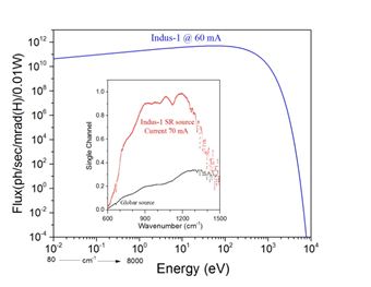 |
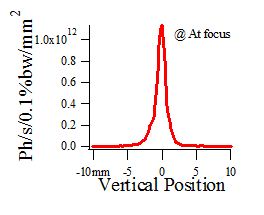
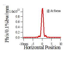
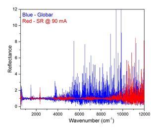
| FIG. (Left) Comparison of thermal source and synchrotron source for 20 µm sample spot size; (Right) Indus-1 flux and single channel spetra from thermal source and synchrotron source. Fluctuations near 1500, 4000 and 7000 cm-1 for SR source are due to transmission dips from window. |
Contact Details:
Shri Himal Bhatt (hbhatt[at]barc[dot]gov[dot]in)
High Pressure & Synchrotron Radiation Physics Division,
Physics Group Bhabha Atomic Research Centre, Trombay, Mumbai - 400085
|