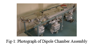
1. Dipole Chamber for Indus-2
- 3571mm (L) x 645mm (W), 22.5° bending angle
- Quantity: 16 Nos
- Material of Construction: AA5083-H321
- Helium leak rate: < 1 X10⁻¹⁰ mbar l/s
- UHV Compatibility: ~ 5 x 10⁻¹⁰ mbar
- Sealing: Helicoflex
- Design : UHVTS , RRCAT
- Machining: HAL, Nasik
- Machining of ports/flanges, Chemical Cleaning, TIG Welding : DMTD, RRCAT:
- Helium Leak Testing, Bakeout & UHV Testing, Installation : UHVTS, RRCAT
|
|
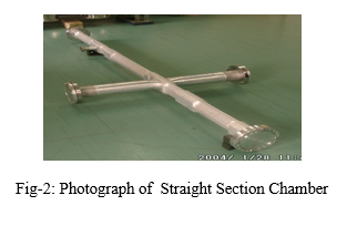
2. Straight Section Vacuum Chambers for Indus-2
- Quantity : 44 Nos
- Length : 950 to 3650 mm
- Material of Construction: AL6063 T6, Al 2219-T851, Al-SS Transition joints
- Helium leak rate: < 1 X10⁻¹⁰ mbar l/s
- UHV Compatibility: ~ 5 x 10⁻¹⁰ mbar
- Sealing: Diamond Profile Al Seal
- Design : UHVTS , RRCAT
- Machining: HAL, Nasik
- Machining of flanges, Chemical Cleaning, TIG Welding : DMTD, RRCAT
- Helium Leak Testing, Bakeout & UHV Testing and Installation: UHVTS, RRCAT
|
|
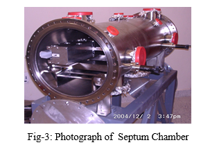
3. Septum Magnet Chamber for Indus-2
- Size: 1392 mm L x 448 mm ID
- Material of Construction: SS316L
- Helium Leak Tightness: Better than 2x10⁻¹⁰ mbar l/s/cm2
- UHV Compatibility: ~ 5 x 10⁻¹⁰ mbar
- End Flange Sealing: Wire seal
- Design : UHVTS , RRCAT,
- Machining, Chemical Cleaning, TIG Welding: DMTD, RRCAT
- Helium Leak Testing, Bakeout & UHV Testing, Installation : UHVTS, RRCAT
|
|
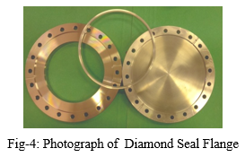
4. Diamond Seal UHV Flange for Indus-2
- Size: DN 40, DN63, DN100, & DN160
- Material of Construction:AA2219-T851/SS316L Seal Cross Ssection : Diamond shape
- Helium leak rate: < 1 X10⁻¹⁰ mbar l/s
- UHV Compatibility: ~ 5 x 10⁻¹⁰ mbar
- Design: UHVTS , RRCAT,
- Machining, Chemical Cleaning, TIG Welding: DMTD, RRCAT
- Helium Leak Testing, Bakeout & UHV Testing and Installation: UHVTS, RRCAT
|
|
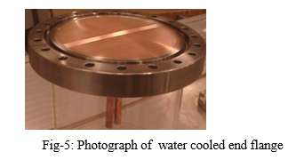
5. Water Cooled End Flange For Indus-2
- Flange Size: DN100, & DN160
- SR Power Density: 800 – 1000 W/cm2
- Material of Construction: OFHC Cu/SS316L
- Sealing : Helicoflex
- Helium leak rate: < 1 X10⁻¹⁰ mbar l/s
- UHV Compatibility: ~ 5 x 10⁻¹⁰ mbar
- Design: UHVTS , RRCAT,
- Vacuum Brazing Process Development & Batch Production: DMRL, Hyderabad:
- Batch Production : LPSC Bengaluru
- Helium Leak Testing, Bakeout & UHV Testing and Installation: UHVTS, RRCAT
|
|
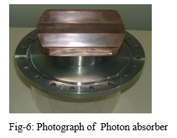
6. Photon Absorber for Indus-2
- Quantity : 64 Nos
- Flange Size: DN100, & DN160
- SR Power : 2 - 4.8 kW
- SR Power Density: 800 – 1000 W/cm2
- Material of Construction: OFHC Cu/SS316L
- Sealing: Helicoflex
- Helium leak rate: < 1 X10⁻¹⁰ mbar l/s
- UHV Compatibility: ~ 5 x 10⁻¹⁰ mbar
- Design: UHVTS , RRCAT,
- Vacuum Brazing Process Development & Batch Production: DMRL, Hyderabad:
- Batch Production : LPSC Bengaluru
- Helium Leak Testing, Bakeout & UHV Testing & Installation : UHVTS, RRCAT
|
|
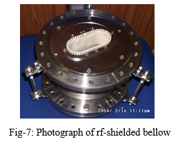
7. RF-Shielded Bellow for Indus-2
- Quantity : 44 Nos
- Size: ID 133mm x 152mm OD
- End Flange: DN160-DSF/CF/HF
- Stroke:15mm Compression, 10mm Expansion
- Material of Construction: SS316L, Be-Cu
- Helium leak rate: < 1 X10⁻¹⁰ mbar l/s
- Ultimate Compatibility: ~ 5 x 10⁻¹⁰ mbar
- Bellow Type: Edge Welded
- Design : UHVTS, RRCAT,
- Fabrication: Indian Industry
- Chemical Cleaning, TIG Welding: DMTD, RRCAT
- Be-Cu Heat Treatment: Glass & Ceramic Components Development Facility, RRCAT
- Helium Leak Testing, Bakeout & UHV Testing and Installation : UHVTS, RRCAT
|
|
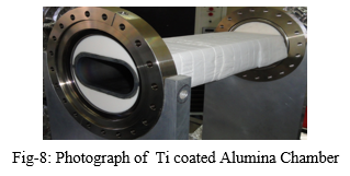
8. Titanium coated Alumina Ceramic Chamber for Pinger Magnet in Indus-2
- Internal Size: 86 mm x 36 mm
- Material of Construction: 99.7% Alumina
- Isostatic Pressing & Sintered
- Ceramic to metal Joint: Active Brazing
- End Flange: DN160-DSF
- Helium leak rate: < 1 X10⁻¹⁰ mbar l/s
- Titanium Coating thickness ~ 0.5 micron
- UHV Compatibility:~ 5 x 10⁻¹⁰ mbar
- Design : UHVTS, RRCAT
- Fabrication: Indian Industry
- Helium Leak Testing, Bakeout, UHV Testing, Ti Coating and Installation: UHVTS, RRCAT
|
|
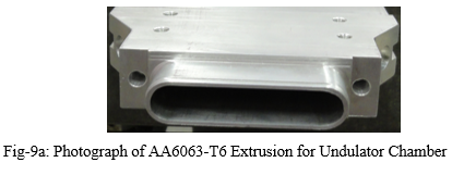
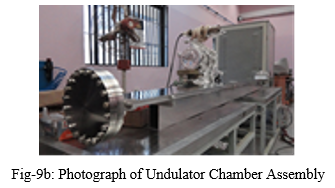
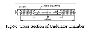
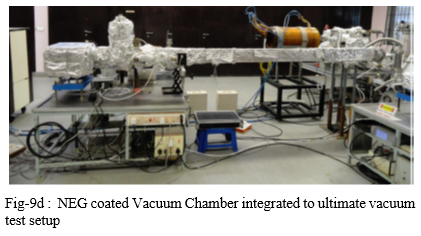
9. NEG coated UHV chamber for Undulator in Indus-2
- Extrusion Material : AA6063-T6
- 81mm(W)x17mm(H) internal x-section, 2700mm L
- End Flange: AA6061-T6, DN160 DSF
- Straightness : 0.2 mm / m
- Molecular flow conductance : 6 l/s/m
- Specific Outgassing Rate: < 1x10-12 mbar l/s/cm2 after bakeout at 170º C X 48 hr
- NEG Coating Chemical Composition: 30% Ti, 30% Zr, 40% V (Atomic %)
- Ultimate Vacuum Achieved (after baking and NEG activation at 180ᵒC) : 8.8 x 10⁻¹² mbar
- Design : UHVTS , RRCAT,
- Fabrication: Indian Industry
- Chemical Cleaning, TIG Welding: DMTD, RRCAT
- Helium Leak Testing, Bakeout, UHV Testing, NEG Coating : UHVTS, RRCAT
|
|
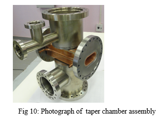
10. Taper Transition Chamber
- Taper transition chamber is required for gentle transition of beam aperture of 86mmx36mm of normal quadrupole chamber to 81mmx17mm of undulator chamber to meet the beam dynamics requirement
- Material of Construction: SS316L & OFE Copper
- Helium leak rate: < 1 X10⁻¹⁰ mbar l/s
- UHV Compatibility: ~5x10⁻¹⁰ mbar
- Design : UHVTS , RRCAT
- Fabrication: Indian Industry
- Chemical Cleaning, TIG Welding: DMTD, RRCAT
- Helium Leak Testing, Bakeout, UHV Testing, NEG Coating : UHVTS, RRCAT
|
|
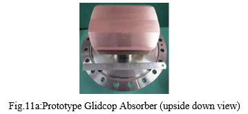
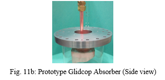
11. Glidcop to OFE Copper UHV Compatible brazed joint
- Material of Construction: Glidcop and OFE Copper
- End Flange: DN160-HF
- Helium leak rate: < 1 X10⁻¹⁰ mbar l/s
- UHV compatibility: ~5 x 10⁻¹⁰ mbar
- Shear strength of the joint was ~ 130 MPa
- Design : UHVTS , RRCAT,
- Machining: Indian Industry
- Brazing: UHVTS, RRCAT
- Chemical Cleaning: DMTD, RRCAT
- Helium Leak Testing, Bakeout & UHV Testing, Installation : UHVTS, RRCAT
|
|
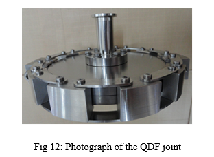
12. Quick Disconnect Flange Joint
- Material of construction: Flange Ti Gr-5, Chain clamp: AA7075-T652, Links: SS316
- Sizes: NW40/160/200/250/300/350
- Sealing: Al diamond profile seal
- Helium leak rate: < 1 X10⁻¹⁰ mbar l/s
- UHV Compatibility: ~5 x 10⁻¹⁰ mbar
- Radiation resistant
- Quick assembly and disassembly (6 to 8 minutes for assembly and 3 to 4 minutes in disassembly for typical NW160 size flange joint)
- Application : Accumulator Ring for IFSR
- Design : UHVTS , RRCAT,
- Machining: Indian Industry
- Chemical Cleaning: DMTD, RRCAT
- Helium Leak Testing, Bakeout & UHV Testing: UHVTS, RRCAT
|
|
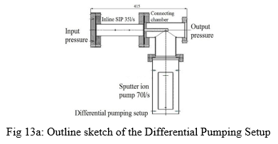
13. Differential Pumping System for Soft X-ray Beam Line of Indus-2
- Differential vacuum pumping system provides windowless transition between high vacuum region (10-6 to 10-7 mbar) and ultra high vacuum region (10-9 to 10-10 mbar) by using series of vacuum pumps and conductance limited openings (tubes).
- It is highly useful for the SRS beam lines where 10-6 to 10-7 mbar pressure is maintained at an experimental station.
- It is supposed to maintain a pressure ratio of 1000 across 415 mm length along beam direction.
- Schematic of the differential pumping setup is shown in Fig 13a.
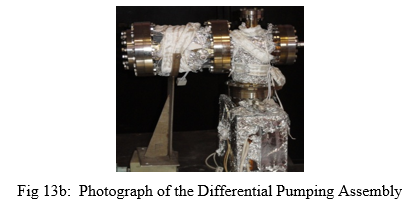
- A two stage differential pumping system was designed, developed in-house, assembled, tested and integrated with BL-3 of Indus-2
- A customised 35l/s in-line sputter ion pump was developed in-house for this purpose.
- Assembly of the system is shown in Fig 13b.
|
|
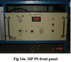
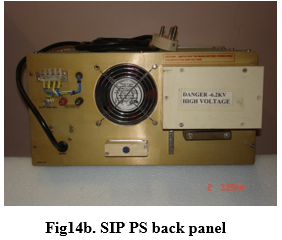
14. Sputter Ion Pump Power Supplies
- Produced by ECIL, Hyderabad
- Model No. SP4806A
- Output voltage at no load 6.2KV DC negative ± 5%
- Output current at short circuit 1000 mA ± 5%
- Line Regulation ± 3 % for ± 10% line variation
- Load Regulation Poor, Drooping Characteristic
- Over load protection Relay cutout for pressure set for 10-5 mbar
- Display: 3½ digit Digital Panel Meter for
- Current ranges 1000mA and 1000μA, Accuracy: ± 5%
- Voltage in K.V
- Input 230V AC, +10%, -10%, 50HZ
- Weight 80 Kgs approx.
- Dimensions 19” x 450 mm x 5U (w x d x h)
- Nearly 100 nos. of SIP power supplies are working on 24x7 basis in Indus accelerators.
|
|
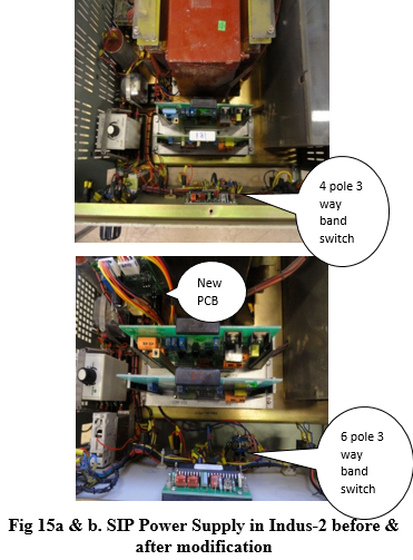
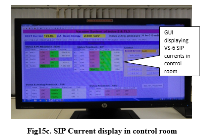
15. Upgradation of SIP power Supplies in Indus-2 and TL-3
- To display SIP current in control room
- SIP current gives an estimation of vacuum and can be correlated with nearby BAG.
- 60 Nos. of power supplies upgraded.
- Current displayed in the range from 1000µA to 1µA
- Corresponds to pressure approx. 1E-07 mbar to 1E-10 mbar
|
|
|
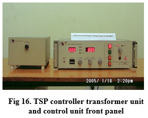
16. Design & Development of Titanium Sublimation Pump Controller
- Mains Supply 230 Volts +/- 10 %, 50 Hz.
- Output Power variable 300 Watts maximum
- Filament Current 1- 60 Amp RMS
- Filament voltage variable 1-5 volts RMS
- Load: ‘U’ hair Pin type of Filament of Ti 85% + 15% Mo.
- Sublimation Pattern – Constant Power at preselected wattage
- Time delay between successive sublimations 1-999 minute maximum for Indus-1 & 1-9999 minute maximum for Indus-2
- Degassing Pattern - Series degassing of pumps of two filaments to maximum 25 amps. RMS in continuous mode, also called BAKE mode.
- Dimensions in mm - 480(L) X 485(B) X 130 (H) Control unit - 210(L) X 280 (B) X 180 (H) Auxiliary unit
- Weight 7 Kg.
- ~ 64 nos. of TSP controllers are working on 24x7 basis in Indus accelerators.
|
|
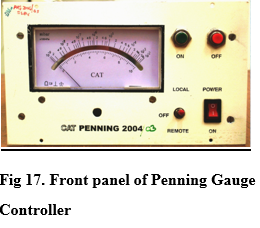
17. Design & Development of Penning Gauge Controllers
Specifications
- Vacuum Range: 10-2 to 10-9 mbar ( 7 decades)
- DC Voltage: -3.2 KV DC
- Permanent Magnetic field:0.14T
Presently these controllers are deployed in TL-2
|
|
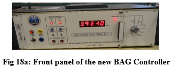
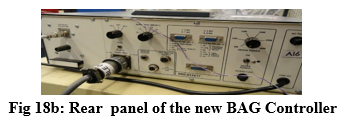
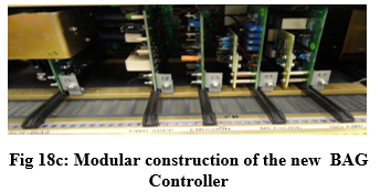
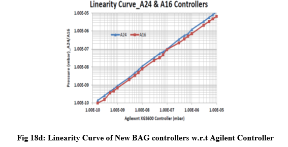
18. Design & Development of new BAG Controllers:
- Modular construction of cards for ease of maintenance.
- 40% reduction in weight and size compared to existing controllers
- Temperature compensation of log amplifier and current Source in Log amplifier card for immunity to ambient temperature variations thereby ensuring better accuracy.
- Filament protection by means of over current sensing, increasing life of filament and thereby reliability.
- Pressure range 10-3 to 10-11 mbar
- Degas power parameter limited to 36 W, enhancing life of filament.
- Fixed discrete setting for sensitivity (10/15/19/20/25 mbar-1).
- Additional process control status provided.
- Isolated output of 0 to 10 V and 4 to 20 mA for remote monitoring
- 32 nos. produced by M/s Aplab Ltd., Mumbai
- Approximately 15 nos. have been installed in Indus-2 and beam lines.
|
|
|
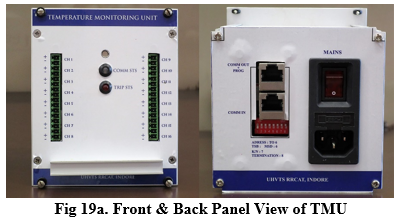
19. 160 Channel Distributed Temperature Monitoring System in Indus-2
- To measure temperatures of dipole chambers, 64 water-cooled photon absorbers & 48 water-cooled end flanges. It provides machine safety interlock in case of a problem. These units replaced old 8-channel units (Fig. 19a).
- No of channels: 16
- Temperature sensor: K-type thermocouple grounded/non-grounded.
- Measurement range : 0-500 °C
- Resolution : 1°C
- Serial communication: Isolated RS-485
- Status available: Trip & serial communication.
- Interlock: provides potential free one contact. The contacts of all trip relays are integrated & single contact is given to Machine Safety Interlock System (MSIS) in case of problem.
- Quick replacement connectors for sensor & RS-485.
- Provision of on-site firmware upgrade.
- 21 such units have been installed in Indus-2.
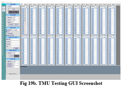
- For initial testing of the units in lab, GUI was developed in visual basic.NET (Fig. 19b).
|
|
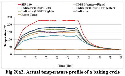
20a. Baking System
- Baking is an essential process for achieving Ultra High Vacuum in vacuum systems.
- It is an intelligent ON/OFF control system, which is designed & developed incorporating modular baking system with distributed controls.
- It contains following blocks:
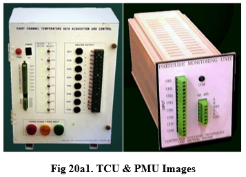
- Temperature controller unit (TCU)Fig 20a1
- Pressure Monitoring Unit (PMU)Fig 20a1
- Baking Application GUI. (Fig. 20a2)
- TCU:
- Number of channels: 8
- Thermocouple Type: K-type
- Resolution : 12 bit
- Sampling Rate: 20 mS
- I/P Signal range: 500 ºC. (+/- 20mV)
- Heater Power/Channel: 4 kW using Short circuit protected SSR
- PMU: For integrated data logging of pressure reading of various gauges along with baking data
- Number of channels: 8
- Input range: 0-10V
- Serial communication: Isolated Rs-485
- Baking application GUI
for overall supervision & control and data logging of temperature & vacuum Main features of GUI:
- Auto/Manual set point provision.
- Supports eight auto set point profiles.
- Supports 8 TCU (48 channels).
- Supports around 8 channel for pressure monitoring gauges.
- Provision for keeping uniform temperature between channels.
- Provision for user notes, channel names & cycle name.
- Status displayed communication status, serial data, heater status etc.
- Data logging in .CSV format & update status displayed.
- Auto recover after power failure.
- PMU support around 12 types of gauges.
|

|
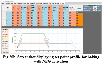
20b. Upgradation of GUI for baking application with NEG activation:
- Upgraded to fulfil the need of dual ramp for NEG coated parts.
- To avoid pre-activation of NEG surfaces.
- In first ramp NEG surfaces are kept ~100 ºC whereas in second ramp they are heated up to ~180ºC.
|
|
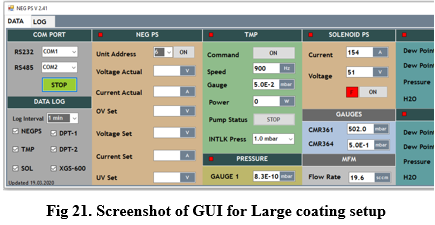
21. Development of centralized GUI for Large Coating Setup
- For the large coating set up in UHVTS lab having various instruments.
- The prototype controller developed is using mbed LPC1768 processor.
Following instruments data is monitored:
- Filament power supply 2U GENESYSTM 3.3kW DC Power Supply.
- Solenoid power supply.
- TMP controller TwisTorr 304 FS AG.
- Vacuum gauge controller TPG 262 for gauge head CMR361 & 364.
- BA Gauge controller.
- Dew point and Pressure Transmitter DPT146 (Qty: 02 Nos).
- Mass flow meter:
|
|
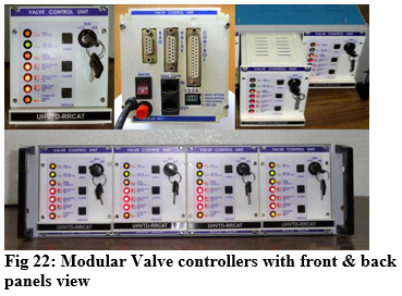
22. Pneumatic Sector & Gate Valve (GV0) Controller in Indus-2
- Indus-2 with a circumference of 172 metres partitioned in 14 vacuum sectors using pneumatically operated RF-shielded gate valves
- 19 nos. of all metal pneumatic Gate Valves installed in the beam lines & two in TL-3
- Valve controllers designed & developed to open the valves during beam filling condition and close them in the event of vacuum failure or any upgradation/maintenance work.
- Salient features of these units:
- Microcontroller based controllers.
- Provides status of valve& latching of interlock status.
- Support for RS232 & Isolated RS-485 communication.
- Local/Remote operation.
- Provides interlock to MSIS if any valve is in not OPEN state.
- Pneumatic pressure interlock using pressure switch.
- Vacuum interlock using BAG near both side of valve.
- Solenoid support 24V/230V.
|
|
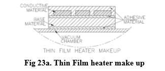
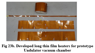
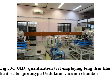
23. Development of thin film heaters for baking & NEG activation of spare Undulator chamber for Indus-2
- To address the issue of decreasing gaps between magnetic elements and vacuum chambers in high brilliance synchrotron light source
- Polyimide film insulated flexible thin heater of thickness ~ 0.6 mm developed indigenously
- Mounted on indigenously developed Al alloy extruded spare undulator chamber for Indus-2
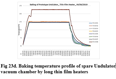
- Baking done at 170 ºC for 48 hrs.
Selection criteria for materials:
- Minimum radiation resistance > 5 MGray
- Design temperature: Maximum: 200ºC; Operating temperature: < 200°C
- Thin & flexible as much as possible.
- Safe, reliable & rugged in working.
- Uniform power densities with excellent electrical insulation properties.
- Duration of Thermal cycle close to ~ 72 hrs.
- Suitable for Aluminum alloy chambers
- Suitable arrangement for tightening / mounting on the chamber
Material Configuration
The thin film heater had four different classes of materials
- Base material
- Conductor Material (Foil)
- Adhesive
- Cover material
- Figure 23d presents the baking profile of ~ 60 hours duration for undulator vacuum chamber with thin film heaters mounted on chamber.
|
|
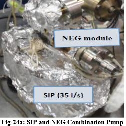
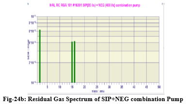
24. Development of Sputter Ion and Non-evaporable Getter Combination Pump
- Pumping Configuration : Triode SIP with NEG module
- SIP Capacity: 35 l/s (N2)
- NEG module Capacity: 400 l/s (H2)
- Material of Pump Body: SS 304L
- Mounting Flange: DN 63 CF (SIP), DN40 CF (NEG module)
- Design : UHVTS , RRCAT,
- Tested at : UHVTS, RRCAT
- Ultimate Vacuum Achieved (after baking and NEG activation): 2.4x10⁻¹¹ mbar
Major Residual Gas at ultimate Vacuum : Hydrogen and minor trace of Methane
|
|
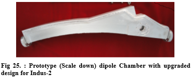
25. Prototype (Scale down) dipole chamber with upgraded design for Indus-2
- Material: AA 6061-T6
- UHV Sealing:Diamond Profile Al
- Joining Method: AC TIG Welding
- Helium leak tighness of joints: No leak above background Helium leak rate of 1x 10⁻¹⁰ mbar l/s
- Ultimate Pr~5x10⁻¹⁰ mbar
|
|
26. Ti Coating of Alumina UHV Chamber for Indus-2 Pinger Magnets
- Alumina UHV chamber required to avoid eddy current effects during pulse operation of pinger magnet.
- Ti coating ~0.5 micron for passage of induced image current
- Ti coating by in-house developed DC Magnetron sputtering setup
- Ultimate Pr~5x10⁻¹⁰ mbar
|

|


