SCRF Cavity Characterization and Cryogenics Section
Material characterization facility
A material characterization facility has been setup to analyze the issues related to cavity development. The facility includes –
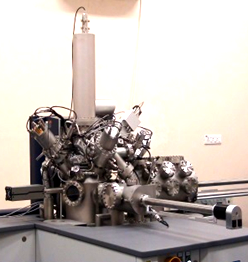
Time of Flight Secondary Ion Mass Spectrometer (TOF-SIMS)
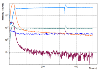
A Time of Flight Secondary Ion Mass Spectrometer (TOF-SIMS) capable of analyzing the impurity distribution in high purity Nb samples after different processing steps. Figure shows the variation in intensity of various impurities (like H, C, O, NbO) across the depth of niobium sample that was prepared by colloidal silica polishing. Depth profiles of the sample was obtained by alternately bombarding the surface with a pulsed Bismuth ion gun for analysis and Caesium ion gun for sputtering.
|
|
Secondary Ion Mass Spectrometer |
Depth profile of impurities of Niobium samples, Total depth = 50 nm (Approximately) |
|
|
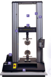
Universal Testing Machine
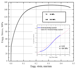
± 50kN Universal Testing Machine, capable of measuring mechanical properties of tensile samples along with plastic strain ratio and stiffness of 9-cell SRF cavity. Figure plots the stress strain curve of a tensile sample from high purity Nb sheet. The yield strength (YS), tensile strength (UTS), uniform elongation (Eu) and strain hardening exponent (n) were found to be 45 MPa, 151 MPa, 30 % and 0.3 respectively.
|
|
Universal Testing Machine |
Mechanical properties of high purity Niobium |
SCRF cavity inspection facility
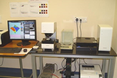
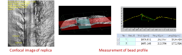
3D Laser scanning confocal microscope
An inspection facility with 3D Laser scanning confocal microscope has been setup for inspection of defects in the cavity. The microscope has a depth resolution of 10 nanometres. A replica moulding facility is also setup to cast replica moulds at the suspicious locations on the internal surface of cavity using Room Temperature Vulcanized (RTV) polymer. These moulds are analyzed using 3D Laser scanning confocal microscope. The microscope is also useful for depth profiling of samples tested using SIMS facility.
|
|
3D Laser scanning confocal microscope |
Optical inspection facility
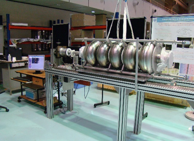
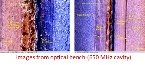
An optical inspection bench is developed indigenously to carry out the internal inspection of a 1.3 GHz 9-cell/ 650MHz 5-cell superconducting RF cavity. The setup can measure the features up to 40 mm/pixel and record the images to analyze the defects on the internal surface of the cavities & weld bead. Tri-color LED lights are used for illumination.
|
A five-cell niobium SRF cavity being inspected using Optical Inspection Bench |
|
View of weld bead at equator of five-cell niobium SRF cavity |
SCRF cavity processing facility
It is a challenging task to produce SRF cavities with high accelerating gradient (> 25 MV/m). To achieve a reliable production of high-performance cavities one needs to couple processing and performance tests in a tight-loop program to observe the variation in the performance of the cavity. It is desired that the required accelerating gradient and quality factor of SRF cavity can be repeatedly produced. The cavity processing includes centrifugal barrel polishing (CBP) and electro-polishing (EP) to produce smooth RF surfaces, high pressure rinse (HPR) stations to remove particulates from cavity surfaces, and vacuum furnace to remove hydrogen. Major sub-systems of cavity processing facilities developed are:
Centrifugal barrel polishing machine
The top surface layer in a SRF cavity up to 100-150 microns is removed by mass finishing operations (CBP & EP). A surface finish of a few tens of nanometres is obtained using barrel polishing. Two centrifugal barrel polishing machine have been setup. One can polish single-cell 1.3 GHz cavities. This machine is largely used for the R&D purpose. The larger machine can polish nine-cell 1.3 GHz and five-cell 650 MHz SRF cavities. The machine has been designed to accommodate up to four SRF cavities. The rotational speed can be varied from 0 to 200 rpm for both the barrel and turret. Finishing media of ceramic and plastic are used along with water for barrel polishing of the cavity. At the start, a coarse ceramic media is used for material removal, followed by finer plastic media for polishing.
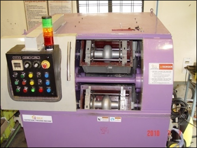
Barrel polishing machine for Single-cell 1.3 GHz SRF cavity
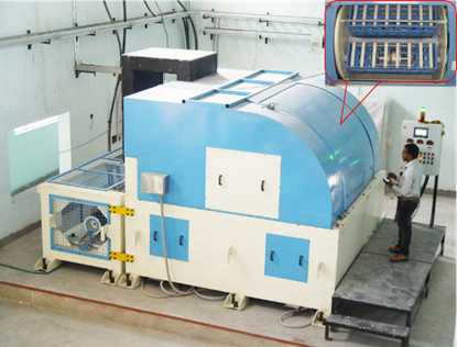
Barrel polishing machine for multi-cell SRF cavities
Electropolishing set-up
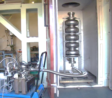
Electro polishing (EP) is an electro-chemical method of removing thin layers of niobium from the cavity surface by anodic dissolution. In the basic electro-polishing set-up, the cavity is the anode and a hollow coaxial aluminium tube is the cathode which is placed along the cavity axis. The electrolyte is a mixture of hydrofluoric (HF) and sulphuric acid (H2SO4). A horizontal continuous electro-polishing setup (Fig.5) is developed for electro-polishing of the niobium cavities.
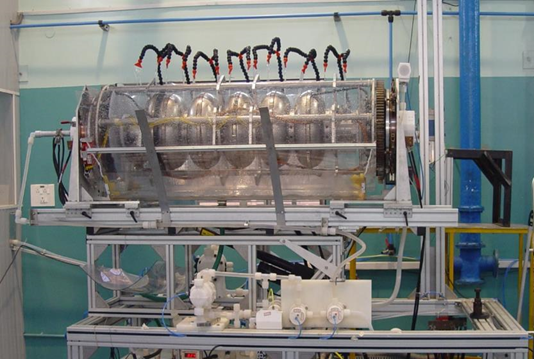
Electro-polishing setup
High Pressure Rinsing Set-up
High pressure rinsing (HPR) is a super-cleanliness process for the surface preparation of high field superconducting cavities. In this process high pressure jets of ultra-pure water dislodge surface contaminants from the cavity surfaces that normally resist removal with conventional rinsing procedures, leading to substantial reduction in field emission and better cavity performance. A rinsing set-up has been developed for this purpose. The set-up comprises of a linear motion system capable of moving 1.4 meter long 650 MHz 5 cell cavity vertically up and down at a speed of 2 to 200 mm per minute and a rotary mechanism to rotate the water jets at 2 to 20 rpm, emerging from fine nozzle tips fitted at the end of a vertical pipe. In order to remove any particulate contaminants in the water generated at the rotary joint, a water filter of 0.05 micron rating has been provided before the nozzles. A teflon diaphragm type pump is used to produce water jets of 100 bar pressure. The set-up shown in Figure is installed in a class 10 (ISO class 4) clean enclosure.
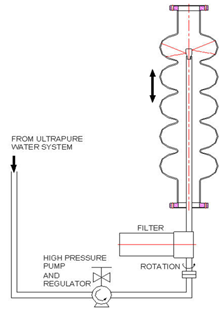 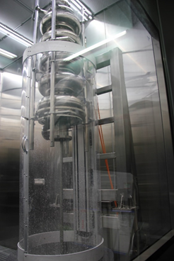
High Pressure Rinsing Setup
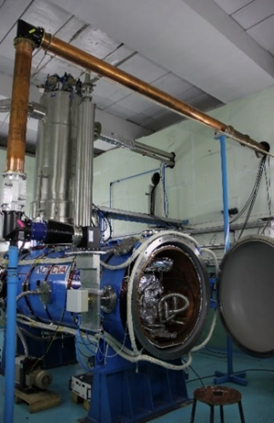
Thermal processing facility
During EP, hydrogen bubbles come in direct contact with the Nb surface which increase absorption of hydrogen. With more than 100 atomic ppm hydrogen dissolved in Nb surface / bulk, there is a possibility of niobium hydride precipitation during cool-down (at around 100 K). This results in reducing the quality factor of the cavity at high accelerating gradient. A furnace treatment at 800°C for 2-3 hours or 600°C for 4-6 hours reduces the hydrogen concentration to a few atomic ppm in the bulk and in the surface layer. For thermal processing of niobium superconducting RF cavities, a dedicated high vacuum annealing furnace has been procured and installed. The furnace has a hot zone of diameter 825 mm and 1525 mm length with a maximum temperature of 1400°C and a temperature stability of ±5°C.
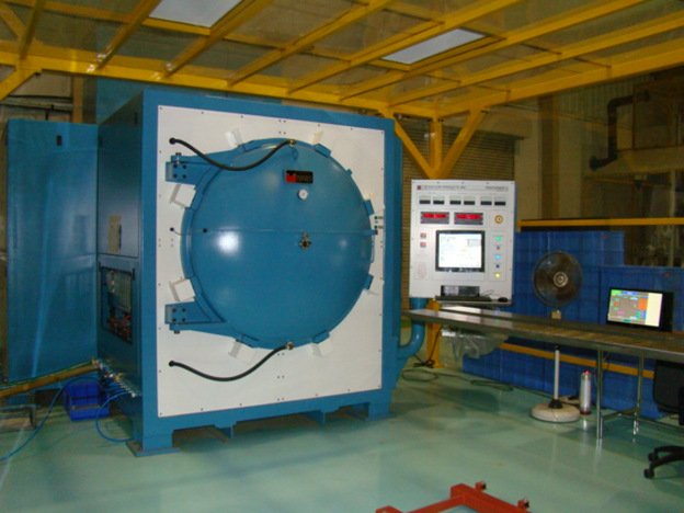
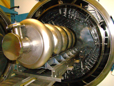
High vacuum annealing furnace
Low Temperature Baking (LTB) Facility
Low Temeprature Baking Facility
ISO-Class 4 clean room facility for HPR and assembly of cavity
A new ISO class-4 cleanroom facility in the cavity processing lab building has been set up for High Pressure Rinsing, Drying and Assembly of multi-cell SRF cavities. Cleanroom has been designed, constructed and validated in accordance with ISO 14644. Cleanroom is divided in 2 classes of air quality, class ISO 4 and ISO 6. To ensure unidirectional laminar flow in the cleanrooms, filtered air is supplied from ceiling mounted ULPA/HEPA filters. Cleanroom areas have a perforated raised flooring to permit return air flow through floor panels. Insid view of cleanroom and pictures of cavity preparation and assembly are shown below.
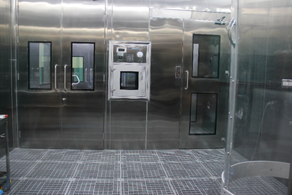
Inside view of ISO class 4 cleanroom
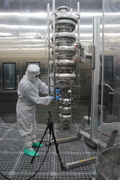
Assembly of 650 MHz 5-cell Niobium Cavity
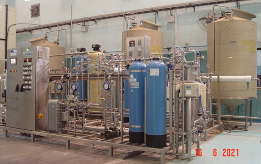
Ultrapure water (UPW) Generation Plant
Final rinsing of 5-cell 650 MHz cavity requires ~ 10000 litres of ultrapure water. To meet this demand, an UPW plant of production capacity 800 LPH with storage capacity of 2500 litres has been installed. Scheme of purification is based on pre-treatment, two pass RO, EDI, mixed bed resin modules, Ultrafiltration and UV sterilization with provision for recirculation of stored ultrapure water for maintaining its purity. Parameters of UPW are given in table below.
Parameter |
Value |
Resistivity |
≥ 18 MΩ-cm |
TOC |
< 30 ppb |
Total Bacteria Count |
< 1 cfu/100 ml |
SCRF Testing Facility
Vertical test stand facility
SRF cavities have to be qualified for their performance prior to installation in a cryomodule of a superconducting linac. First, the bare cavities are tested in a saturated bath of liquid helium at a temperature of 2 K in the Vertical Test Stand (VTS). Cavities, qualified in VTS are then dressed with their auxiliary equipments, like helium vessel, HOM couplers, cold tuner and main coupler. These dressed cavities are then tested in a Horizontal Test Stand (HTS).
The vertical test stand consists of a large size liquid helium cryostat, an RF power supply and control system, and a liquid helium (LHe) and liquid nitrogen (LN2) piping system. The SRF cavity is tested for the quality factor (Q) and accelerating gradient (E) at 4.2 K and 2 K.
A liquid helium cryostat assembly comprises of an ASME Code stamped stainless steel helium vessel, process tubing for flow of helium. The helium vessel and helium tubing are thermally shielded with a liquid nitrogen cooled thermal shield. The assembly of LHe vessel and thermal shield is housed in a stainless-steel insulating vacuum vessel wrapped in multilayer super-insulation for reducing heat leak. The cryostat has an overall dimension of diameter 1370 mm and length of 5420 mm. The cryostat is mounted with cryogenic control valves for the supply of liquid helium, liquid nitrogen and a parallel plate vacuum relief valve. A schematic of the cryostat assembly is shown below:
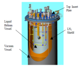
A schematic of VTS cryostat assembly.
A cavity insert assembly supports the cavity in the liquid helium bath during the testing. It consists of a stainless-steel top plate with several penetrations for RF cables, active cavity vacuum pumping and connections for cavity diagnostics. The cryostat assembly is installed below the ground level in a pit. The pit is covered with a movable radiation shielding lid during testing of SRF cavities.
Two-layers of cylindrical magnetic shields are incorporated in the cryostat to reduce the residual magnetic field to less than 1μT in the cavity region. The design incorporates a room temperature outer shield made of 1mm thick Mu-metal and an inner shield with perforated end cap at the bottom (for LHe flow), in 1mm thick ammuneal 4 K (A4K) material.
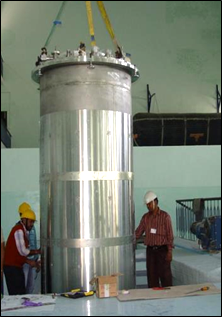
VTS cryostat assembly.
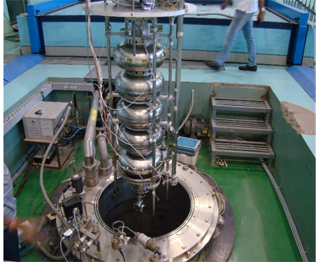
Assembly of VTS insert with 650 MHz cavity with cryostat
VTS Facility
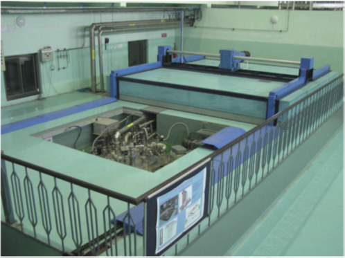
Horizonal Test Facility
The Horizontal Test Stand (HTS) facility is commissioned at RRCAT for high power testing of dressed five cell 650 MHz superconducting RF (SCRF) cavities at 2 K temperature. The HTS facility comprises of a cryostat, cryogenic distribution system, high power RF system, 2K pumping system, low level RF control, RF protection & interface, control & safety system etc. The cryostat is capable of cooling down two SCRF cavities simultaneously. Liquid nitrogen and helium are supplied to the cryostat through in-house fabricated cryogenic transfer lines. A five cell 650 MHz dressed SCRF cavity was successfully tested in HTS. During this test the cavity was first conditioned for more than 20 hours, at pulse repetition rate of 20 Hz with duty cycle upto 40% and power up to 22kW. After conditioning cavity was operated at gradients of up to 14.8 MV/m in CW (Incident power 8.8 kW) and 19.9MV/m in pulsed mode (20 Hz, 40% duty cycle and with 22 kW incident power). Successful commissioning of HTS is an important milestone in development of superconducting cavities as it completes a full development cycle of fabrication, processing, tuning, dressing and testing of superconducting cavities at RRCAT.
|
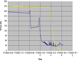
Cryogenic circuit cooldown
|
Dressed cavity ready for testing in HTS |
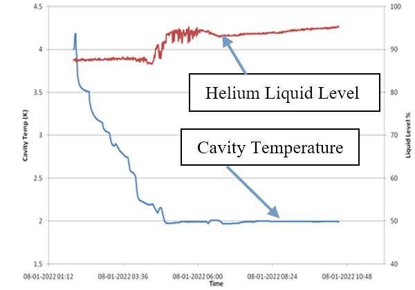
Helium Liquid level and cavity temperature with time |
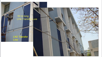
In-house fabricated cryogenic transfer lines |
|


