|
505.8 MHz RF cavity for Indus-2
Indigenous development of RF cavity was taken up to cater the need for additional RF cavities for operation of insertion devices and to provide ease of operation and spare for the aging previously installed RF cavities. 505.8MHz indigenous bell-shaped oxygen free copper RF cavity has been designed, developed, tested, installed and commissioned in synchrotron radiation source Indus-2.The development of RF cavity is a complex multidisciplinary activity involving expertise in fields of electromagnetics, thermal, mechanical, fabrication, higher order modes, vacuum technology, RF characterization and beam instabilities. All components were machined in RRCAT workshops with oxygen free electronic (OFE) copper plates and bars. Vacuum Brazing was carried out in three stages followed by torch brazing and TIG welding
|
|
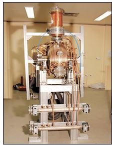
Fig. 20: Fabricated RF cavity |
Fig. 21: View of installed RF cavity in Indus-2 |
Strict tolerance control on all brazing surfaces and geometrical accuracy within 0.25 mm on inner profiles is achieved. Alumina abrasive polishing followed by chemical processing is carried out to achieve high surface finish (Ra 0.25 µm) and cleanliness on inner surfaces of the cavity, compatible to high RF fields and ultra-high vacuum. All joints were leak tested up to of 5x10-11 mbar-litre/sec.A high power RF input coupler consisting an alumina ceramic window and water cooled inductive loop is designed and fabricated. After fabrication and vacuum leak testing, baking of the cavity was performed by hot water at 150 °C at 6 bar pressure through all the copper tubes for 36 hours. After cool down a vacuum level of 2x10⁻⁹ mbar in the cavity is achieved. Conditioning and high power test was carried out in a high power test set up to 33kW resulting in ultimate pressure of 4x10⁻¹⁰ mbar. The resonant frequency was measured to be 505.488 MHz and unloaded quality factor is estimated to be 39,900. Instabilities due to HOMs are suppressed by varying the temperature of precision chiller of cavity and HOMFS position. HOMs measurements are performed by varying the tuner position, HOMFS position and with variation in cavity body temperature. Tuner and Temperature coefficient were calculated and found within tolerable limits.
The RF cavity was installed in long straight section (LS-7) of Indus-2 along with all subsystems.At the optimized RF and HOM settings (cavity temperature and HOMFS position), more than 200mA at 2.5 GeV beam operation is attained in Indus-2 with total RF power of 55kW and operating at cavity gap voltage of 350kV.
|