 Switch Mode Power Converter Section (SMPCS)
Power Converters for Indus Complex
Switch Mode Power Converter Section (SMPCS)
Power Converters for Indus Complex
The source of electrons for the Indus Accelerator Complex is a microtron. The electrons are then transported via transport Lline-1 (TL-1) to booster synchrotron, where their energy is further increased. The high-energy electrons are then injected to Indus-1 storage ring via Transport Line-2 (TL-2) and to Indus-2 via Transport Line-3. SMPCS is responsible for the design, development, installation, operation and maintenance of the following power converters for various magnets in these parts of Indus Accelerator Complex:
|
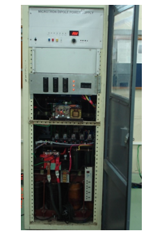
Power Converter for Microtron Dipole |
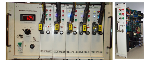
Power Converters for Microtron LH/RH Coils, TL-1 Quadrupole and Dipole Magnets
The power converters for LH/RH coils of microtron (5 A, 10 V, 2 nos.), TL-1 quadrupole magnets (5 A, 12 V – 6 nos.) and TL-1 dipole magnet (12 A, 14 V, 1 no.) are based on two switch forward converter operating at 100 kHz switching frequency. The power converter design has been standardized on 6U card, allowing easy interchangeability to reduce downtime of the system. Sufficient spare power converter cards are also provided on site. The power converters are more efficient, lighter and smaller.. Output current stability of all the power converters is better than ±100 ppm.
|
TL-1 quadrupole and dipole power converters |
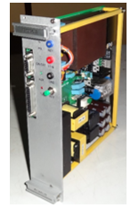
Power Converter for Energy Analyzer Magnet
The power converter for energy analyzer magnet is rated for 10 A/ 18 V output with output current stability of ±100 ppm. The topology used is two-switch forward converter operating with variable frequency PWM (VFPWM) control in the range from 20 kHz to 100 kHz. In order to achieve better stability, oven is used in the front end electronics. This power converter has the capability to be operated in remote mode. To monitor various signals, a 9-pin D-connector is provided on the fascia plate.
|
Energy analyzer magnet power converter |
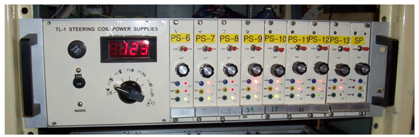
Power Converters for TL-1 Steering Coils
The power converters for TL-1 steering coil magnets are rated for 500 mA and 20 V maximum. A MOSFET-based linear regulator scheme has been selected for this power converter due to low power rating and to maintain simplicity. Each power converter has been designed on a single 3U size PCB, with full-function feedback control and local-remote operation interface electronics on the same card, for standard 19-inch rack assembly.A common multi-secondary step-down transformer is used to provide necessary ac input voltage to each power converter card, wherein it is rectified, filtered and fed to the MOSFET linear regulator.
|
TL-1 steering coil power converter sub-rack |
TL-1 Combined function steering coil power supplies
These two power supplies rated for 20V/10A are a new addition in Transport line -1 just after Microtron. Salient features of these power supplies are: nearly unity power factor at the input, bipolar load current, smooth transition from one polarity to other. Power stage consists of a boost converter at the input to ensure unity power factor, a full-bridge inverter to achieve isolation as well as required voltage at the loadfollowed by full bridge inverter for changing polarity of the load current. For more details, please click here.
Booster Main Power Converter
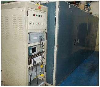
In booster ring, trapezoidal current is made to pass through a series circuit comprising of mains coils of 6 dipole magnets and 6 pairs of QF and QD magnets using this power converter. Current is ramped up from a low value corresponding to injection beam energy from microtron to higher values corresponding to injection energies of Indus-1 and Indus-2. The ramp rate of current rise and fall is 2000 A/s. The cycle repeats at every 1 s.
In booster dipole power supply, two three-phase SCR bridges are put in series constituting a 12-pulsed rectifier system. A complex feedback loop system provides the necessary current wave shape and maintains the needed current stability. Precise timing of the current waveform is crucial for accurate injection in booster ring. All other power supplies in Booster ring (adjustment coils for quadrupole magnets, horizontal and vertical steering magnets) follow the same current profile.
|
Power converter for booster dipole magnet |
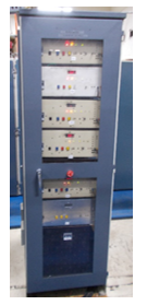
Booster Vertical Steering Coil Power Supplies
These power supplies feed five independent vertical steering coils with Booster ramp current profile (peak current rating of 20A). These are true bipolar power converters. They are developed using linear power amplifier schemes. They also follow the ramp current profile as other booster magnets.
|
Booster vertical steering coil power converters |
Power Converters for TL-2 Dipole Magnets and Indus-1 Quadrupole Magnets
These power converter (300 A, 120 V maximum) are developed using a novel full-bridge zero-voltage-switching (ZVS) converter in which the IGBTs are operating at 25 kHz. The converter has a passive adaptive energy storage circuit. When the output current is set at the lower values resulting in low stored energy in the leakage inductance., the auxiliary circuit stores more energy. On the other hand, when the output current isset at the higher values resulting in sufficient stored energy in the leakage inductance to achieve ZVS, the auxiliary circuit stores less energy. Thus the ZVS over full range is achieved without increasing the conduction loss. Output current stability is measured to be better than ± 40 ppm, which is well within the specification of ± 400 ppm.
|
TL-2 dipole and Indus-1 quadrupole magnet power converters |
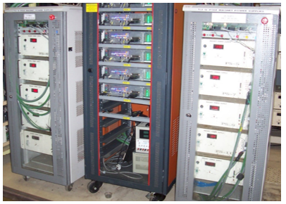
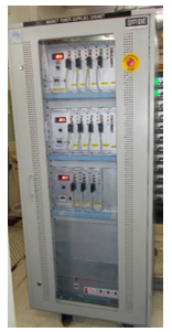
Power Converters for TL-2 Quadrupole Magnets
There are 8 quadrupole magnets in TL-2 which are powered by 8 independent converters of rating (80 A, 25 V). Topology used in these converters is two switch forward converter operating at 50 kHz switching frequency. Each of the power converters is housed in one 4U rack and eight such power converters are housed in two 24 U cabinets. Each cabinet also has the provision for one spare power converter for easy replacement in case of problem to minimize the machine downtime.
|
TL2 quadrupole magnet power converters |
Transport line-2 Steering coil power converters
These 11 power converters are meant to energize independent steering coil magnets for horizontal and vertical correction of electron beam. The topology used in these power converters is two-switch forward converter operating with variable frequency PWM (VFPWM) control in the range from 20 kHz to 100 kHz. In order to achieve better stability, oven is used in the front end electronics. A polarity reversal scheme has been implemented in order to change the polarity of output voltage. To monitor various signals, a 9-pin D-connector is provided on the fascia plate.
|
TL2 Steering coil power converters |
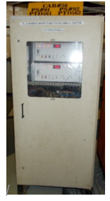
Transport line-3 Dipole Magnet Power Converter
The TL3 dipole magnet power converters energize three dipole magnets of Transport Line-3. These power supplies are developed using 12-pulsed SCR regulator. All power devices and magnetic components are water-cooled. Two independent power supplies for BM1 and BM2 are housed in one cabinet - they only share a common cooling water connection. Power supply for BM3 is housed in another cabinet.
|
TL3 Dipole Magnet Power Supply |
Indus-1 dipole magnet power converter
This power converter rated for 140V/800A DC is used to energize series string of 4 dipole magnets in Indus-1 ring. The required current stability is ±100 ppm. This power supply also uses a 12-pulsed SCR regulator and filter with associated feedback loop to achieve these parameters. All power components – SCRs, transformer, and filter inductors are water-cooled.
|
Indus-1 dipole magnet power converter |
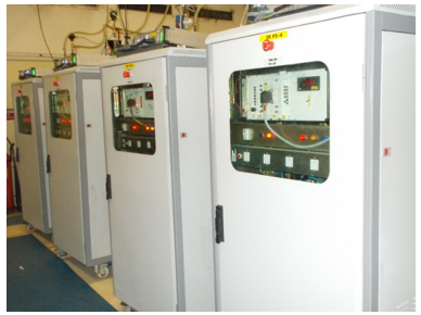
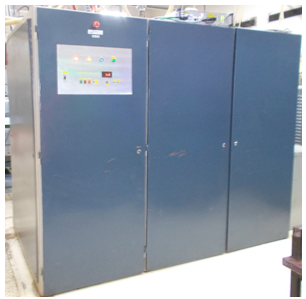
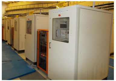
Power Converters for Indus-2 Quadrupole Magnets
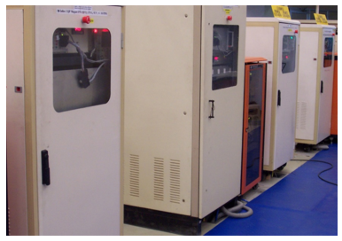
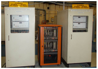
Two topologies have been followed for the development of power converters for quadrupole magnets of Indus-2. At present, the power converter for Q1 and Q2 type quadrupole magnets are developed using transistor series pass scheme with twelve-pulse SCR rectifier as pre-regulator whereas the power converters for Q3 type quadrupole magnet are developed based on two-switch forward converter topology, in which two stages of two-switch forward converters (each rated for 60 V, 180 A) are connected in input-parallel and output-series configuration. This resulted in modular and smaller units, better thermal management, simpler configuration, smaller filtering requirements and better layout for easy maintenance.
|
Power converters for Q1 type magnets in Indus-2 |
|
Power converters for Q2 type magnets in Indus-2 |
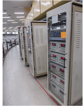
|
Photograph of power converters for Q3 type magnets in Indus-2 |
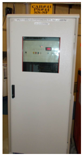
Power Converters for Indus-2 Skew-Quadrupole Magnet
Skew quadrupole coils are fitted on sextupole magnets. Total 4 power converters are required to energize these coils. These power converters are similar to those for TL3 dipole magnets and are developed using 12-pulsed SCR regulator. All power devices and magnetic components are water-cooled. Two independent power supplies are housed in one cabinet - they only share a common cooling water connection.
|
Power converter for skew-quadrupole magnet in Indus-2 |
Power Converter for Indus-2 Sextupole Magnets
There are two families of 16 sextupole magnets (SF and SD) in the ring. All the 16 magnets in each family are connected in series. Each string is energized by separate power converter. The power converters are developed using 12-pulsed SCR regulator followed by a filter. A saturable inductor is also used in filter circuit so as to reduce the minimum continuous conduction current. All power devices and magnetic componentsare water-cooled.
|
Power converter for sextupole magnet in Indus-2 |
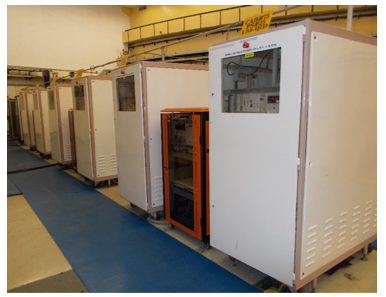
Power Converters for Steering Coils in Indus-2 and TL-3
Power stage of these power converters consists a full-bridge ac-dc converter to achieve isolation as well as required voltage at the load, followed by full bridge inverter for changing polarity of the load current. Total 111 power supplies required are arranged in 15 numbers of 32U cabinets. Each 32U cabinet is equipped with 4 numbers of 4U boxes. Each 4U box contains two power supplies. All these power supplies are operated by single phase, 230V, 50Hz.
|
Steering coil power supplies on Indus-2 gallery |