|
Beam Diagnostics & Coolant Systems Division
|
|
Beam Diagnostics Section
|
|
Indus-2 Beam Diagnostic Systems
The diagnostics system of Indus-2 consists of the following beam monitoring devices.
- Beam Position Indicator
- Beam Profile Monitor
- DCCT
- Stripline
- Scraper
- Wall Current Monitor
- Sighting Beam Line
- Septum Hole Monitor
- X-ray Diagnostic Beamline (BL-24) at Indus-2
- Visible Diagnostic Beamline (BL-23) at Indus-2
- Diagnostics for H- Linac
- Setup for Calibration of Beam Position Indicators of Indus-2
A synopsis of the diagnostic systems is given in table 1. Description of these devices is given below.
1) Beam Position Indicator
Function
Beam position indicator (BPI) is used to measure the position of the charge centroid of the electron beam circulating in the accelerator vacuum chamber. Four-button electrodes type BPIs are being used in Indus-2 for the measurement of electron beam position at 56 locations (40 numbers of individual type BPIs + 16 numbers of integrated to dipole vacuum chambers). Since it is a non-interceptive type device, it can measure the beam position without disturbing it. There are 56 BPI in the ring, 7 in each cell. Out of these, 40 BPI are of individual type and 16 are integrated type. One integrated type BPI is embedded in each dipole chamber. Using these beam position indicators, the position of the equilibrium beam orbit and closed orbit distortion (COD) are obtained. This data is used by the control system to correct the COD.
Principle of operation
The device consists of four button shaped electrodes mounted symmetrically in the cross section of the accelerator vacuum chamber. The electrode connection is brought out of the vacuum chamber by means of vacuum feed through coaxial connector. The electron beam has an electromagnetic field associated with it. When the electron bunch passes through the BPI, beam electric field induces charge on the electrode. The signal induced on the electrode can be modeled as either voltage or current source depending on the bunch length and the product of electrode capacitance (C) and external circuit resistance (R). The signal induced on an electrode depends on the proximity of the beam to that electrode. The beam position with reference to the geometric center of the device can be obtained by detecting the four electrode signals and applying a suitable position algorithm. The relationship between the beam coordinate obtained through the algorithm (“electrical coordinate”) and the actual coordinate (“mechanical coordinate”) is, in general, nonlinear. The nonlinearity
depends on the vacuum chamber geometry and the placement of electrodes. This relationship is obtained by calibrating the BPI on a test bench, in which an antenna excited by an RF source is used to simulate the beam. This calibration is done before installing the BPI in the accelerator.
Construction details
(1) Individual Type Beam Position Indicator (Qty : 40 Nos)
These individual type beam position indicators for Indus-2 are made of stainless steel. The total length of this monitor is 100 mm including rotatable flanges of thickness 22.3 mm each (outside diameter of 203 mm) on both the sides. There are four button electrode assemblies in each BPI. A holding & supporting device is used for the installation of BPI. This device provides required movement during alignment of BPI. Once the alignment is completed, this device holds the BPI in aligned condition during the operation of Indus-2.
Existing beam position indicators (BPIs) were installed approximately 13 years back in Indus-2 synchrotron radiation source and they are operational since then. Keeping in view the present requirements regarding the performance improvements of existing installed BPIs, these are being replaced in phased manner with upgraded beam position indicators (UPBPIs) having improved design features. The individual type BPIs have been replaced with UPBPIs at 21 locations. For the remaining locations, the development of UPBPIs is in advanced stage.
UPBPI has improved design features like high frequency compatible 50 Ω impedance SMA feedthrough, Nd:YAG laser welded electrode assembly, transfer impedance ~ 0.56Ω @505.8 MHz and sensitivity ~ 0.06 per mm in both the transverse planes. It has Ø11.8 mm button diameter. Before the installation, each of the UPBPI has been subjected to helium leak test followed by UHV performance test (~ 4x10E-10 mbar ultimate pressure achieved) and calibrated using coaxial wire method. These UPBPIs with digital processing electronics are being used during continuous operation of Indus-2 ring since Dec 2014 to monitor the position of beam with better resolution with respect to the old BPIs thus minimizing the close orbit distortions of the beam which results in delivery of a more stable photon beam for the beamlines users. The upgraded beam position indicators of Indus-2 have been installed at the dedicated holding & supporting devices.
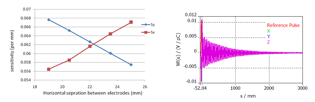
Figure 1: Horizontal and vertical sensitivity as a function of button separation. Wakefield (Volt/pC) as function of distance after the bunch (mm) for bunch length: 10mm.
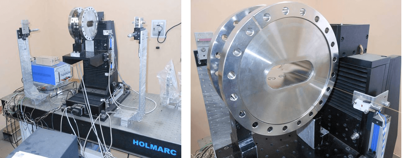
Figure 2: Upgraded BPI during lab qualification
Figure 3: Batch of upgraded BPIs during UHV qualification
Figure 4: Upgraded Beam Position Indicator of Indus-2 installed at holding & supporting device (upper half made of SS with μr ≤ 1.080, lower half is sand filled to damp the ground vibrations)
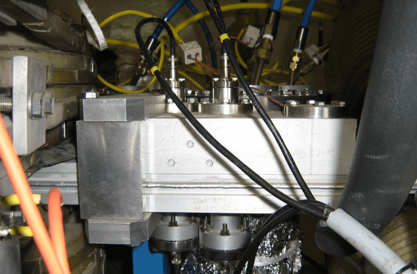
Figure 5 : Integrated Type BPI of Indus-2
Integrated BPI
UPBPI
In order to provide a BPI integrated with dipole chamber, 4 nos bores (2 nos in upper half and 2 nos in lower half) are made during the machining of dipole vacuum chambers of Indus-2 ring. The electrode assemblies are inserted directly in the 2 nos of bores provided in upper half of dipole chamber. In lower half of dipole vacuum cahmber, 2 nos of sleeves are welded and then electrode assemblies are inserted in these welded sleeves. The material of construction of dipole is aluminium alloy. The material of electrode assembly involves Macor® discs and SS parts. Fig.2 shows the integrated type BPI in the dipole vacuum chamber of Indus-2 ring.
Processing Electronics:
The signal induced on the electrode contains harmonics of the bunch revolution frequency. As the signal contains high frequencies, signal processing is necessary before an ADC can acquire it. In Indus-2, narrow band processing scheme is used. The processing electronics is based on the principle of multiplexed tuned receiver. The electrode signals are transported to the electronics rack kept on equipment gallery through a multi-coaxial RG 223/U cable. There are eight electronics racks distributed symmetrically on the equipment gallery. The output of the processing electronics is acquired by 4-channel, 16 bit ADC cards and the acquired data is transferred to the control room, where beam position is calculated by using position algorithm.
(3) Ultra high compatible beam position indicator assemblies for APPLE-2 undulator vacuum chamber for Indus-2 ring.
The design, development and installation of ultra high compatible (UHV) beam position indicator assemblies for APPLE-2 undulator vacuum chamber for Indus-2 ring have been carried out. This assembly is a low gap type diagnostic device which is used to monitor the position of electron beam precisely at the upstream and downstream ends of APPLE-2 undulator vacuum chamber for Indus-2.
Description
UHV compatible beam position indicator assemblies for APPLE-2 undulator vacuum chamber for Indus-2 ring have been designed, developed and installed at the upstream and downstream ends of vacuum chamber. It is used to monitor the position of electron beam precisely at the installed locations by using four numbers of capacitive pick up type button electrodes. CST Studio Suite simulation tool was used for the physics design in order to achieve the important requirements of this low gap type beam position indicator like a resonance free structure over wide bandwidth, transfer impedance ~ 0.7Ω @505.8 MHz (targeted value > 0.5Ω) and sensitivity ~ 0.125 per mm (targeted value > 0.1 per mm) in both the transverse planes. This UHV compatible assembly has internal race track profile having aperture 17 mm (V) x 81 mm (H), same as of vacuum chamber of APPLE-2 undulator. It incorporates four numbers of electrode sub-assemblies directly welded by tungsten inert gas (TIG) welding method on its body. The diameter of button electrode is 9 mm. The horizontal separation between button electrodes is 12 mm. A machinable dielectric (Macor®) spacer is used to insulate button electrode from grounded body. An in-house developed 250 W average power fiber-coupled pulsed Nd:YAG laser has been utilized for laser welding to integrate button electrode at the central conductor of SMA feedthrough. RF-shielded hydroformed bellow sub-assemblies have been integrated at the both ends which reduces mechanical coupling and ensures the electrical continuity at high frequencies. The total length of UHV compatible beam position indicator assembly for APPLE-2 undulator is 250 mm.
The flushing accuracy of button electrode, with respect to the inner wall, is better than 50 μm. Obround shaped 1.5 mm thick weldable lip on both sides were designed for UHV compatible full penetration TIG welding of bellow end plate. Further, 0.6 mm thick circular lip for edge joint welding with 0.4 mm thick lip of SMA by TIG welding were also designed. The complete assembly has been vacuum characterized up to the ultimate vacuum of ~9x10E-10 mbar. The calibration was done and sensitivities were measured using coaxial wire
method. The value of measured sensitivities were found closely match with the theoretical designed value.
A holding and supporting device has also been designed, developed and installed using low thermal expansion materials, 36% Ni-Fe alloy and carbon composite, in order to minimize the change in mechanical center ~ 2μm / oC (targeted value < 5μm / oC) due to any change in the ambient temperature.
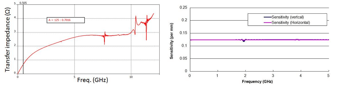
Figure 6: Transfer impedance as a function of frequency Figure 7: Sensitivities as a function of frequency
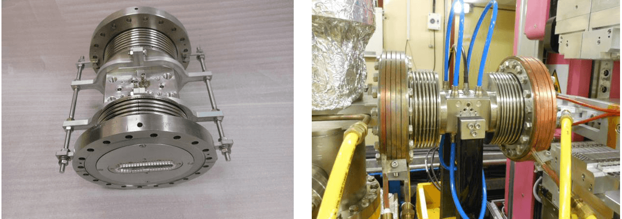
Figure 8: Beam position indicator assembly for APPLE-2 undulator Figure 9: Beam position indicator assembly for APPLE-2 undulator
2) Beam Profile Monitor
Beam profile monitor (BPM) is a destructive type of diagnostic device used with high-energy electron beam. This type of monitor converts information of the electron beam intensity profile in to visible light intensity profile. BPM is used for visual observation of the beam shape and position. This information is used to set the magnet currents so that the beam is steered in the right direction and the beam is optimally transported through the transfer line. It also helps in closing the first turn of the beam in the storage ring during the commissioning trials. BPM is not used during the operation of the accelerator.
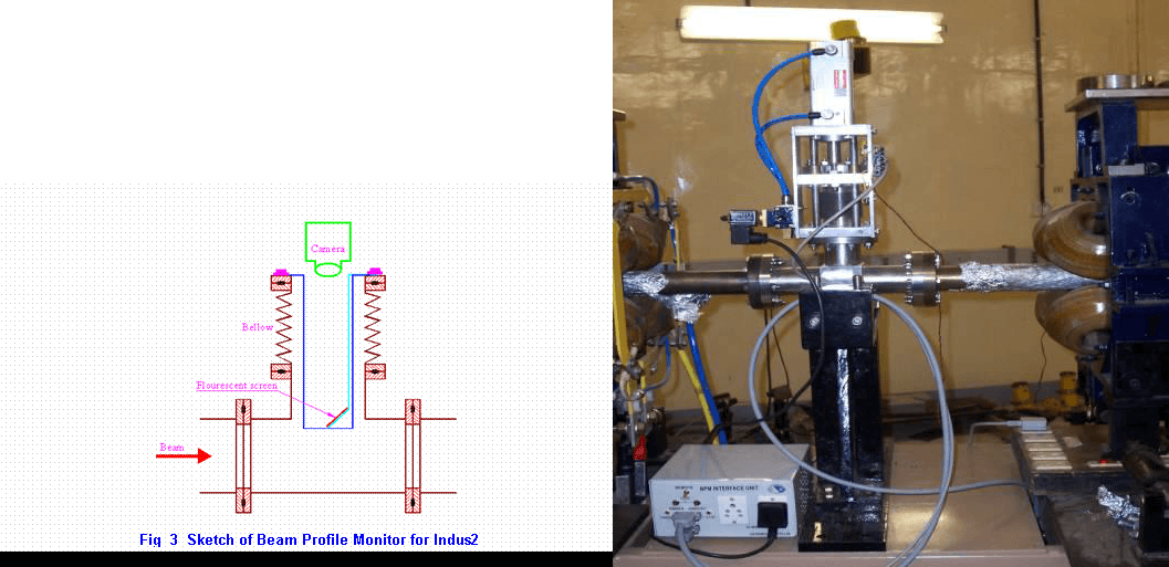
Figure 10 : Beam Profile Monitor of Indus-2
Principle of operation
Beam profile monitor is essentially a florescent screen placed at 45° with the axis of the beam. Screen is inserted in to the beam and the TV camera or CCD views the visible photons produced due to the scintillation. Qualitative analysis of profile of the beam does not require complex electronic post processing, profile can be seen directly on the video monitor. For the quantitative profile and intensity it needs bit complex electronic post processing but still relatively less complex than other diagnostic devices.
Construction details
Cr doped Al2O3 is used as fluorescent screen, which is supported in a pipe which isolates the screen from vacuum. On the other hand, screen is out side the vacuum, which enables easy maintenance of the screen without affecting the vacuum. As only the end positions of screen are of concern rather than intermediate position, therefore screen is inserted in to the beam with its support, by pneumatic actuator. Pneumatic actuator is double acting piston cylinder arrangement with end cushioning. Valves of pneumatic actuator are operated by solenoid coil. Limit switches are used to have the information regarding the position of the screen. Fluorescent screen and its support are housed through edge-welded bellow. The edge welded bellow accommodates to and fro motion across the vacuum containment. On the other hand edge welded bellow is used to transmit linear motion across vacuum boundary.
Support assembly of fluorescent screen together with bellow and body of BPM forms a vacuum enclosure. The body of BPM is made up of SS 316L because of its relatively good vacuum properties such as low vapour pressure, low out gassing rate, low gas permeability, good mechanical properties such as high ultimate and yield strength, good corrosion resistance. It shows appreciably high strength at elevated temperature. And high melting point enables it to undergo vacuum conditioning at high temperature.As the vacuum of the order of 10-10 Torr is to be maintained, CF 63 flanges are used to have ultra high vacuum compatible sealing. Fig.3 shows the drawing of the TL-3 BPM assembly.
BPM Electronics
As the number of BPM installed in TL-3 and storage ring is large, the video signals from the CCD cameras need to be multiplexed. A VME based 8 to 1 video multiplexer card has been developed. Such three cards are used in the system, which are housed in the VME EIU racks. The CCD camera output is transported to the multiplexers through RG59 B/U video cables. The multiplexer output is transported to the control room where beam profile is displayed on video monitor. BPM interface units are used near each BPM to convert the high-level control commands in to the actuating signals for various components of the BPM.
Operation
The beam profile monitor is operated remotely from the control room. Depending on the user requirement, any BPM can be activated by issuing command to the control system. The status of the BPM is also available in the control room. When the screen is inserted, the beam is partially stopped at that location. The beam spot at that location is seen on the video monitor in the control room.
3)DCCT
Function
DCCT is used for measuring stored (average) beam current circulating in the storage ring. The beam lifetime is found out by plotting the decay of stored current with respect to time. The DCCT used in Indus-2 has two measurement ranges of ±100 mA and ±1 A. It consists of a toroidal core mounted on the vacuum chamber. An insulating gap is provided in the vacuum chamber to prevent the flow of dc and low frequency currents in the vacuum chamber wall passing through the core.
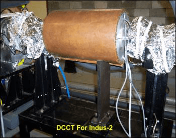
Figure 11: DCCT for Indus-2
The insulating gap is bypassed with capacitors to provide low impedance path for high frequency currents. This prevents the core from getting exposed to high frequency EM field of the beam and resulting heating of the core. The front-end electronics is kept near the core and back-end chassis is kept in the instrumentation rack on the equipment gallery.
DCCT Vacuum Chamber Details
The DCCT torroid is mounted on the outside of a stainless steel vacuum chamber. In order to interrupt the electrical conductivity in the vicinity of vacuum chamber, a ceramic section is brazed to the chamber. To protect the sensor from being heated beyond 700 C during vacuum chamber bake-out, it is mounted over a water cooled copper cylinder. To protect the sensor against strong magnetic field, a two layer magnetic shield is provided. Outer shield comprises of 1.5 mm thick low-carbon steel, which is having high saturation field. The inner shield is made of 0.8 mm thick mu-metal, which presents a high magnetic permeability. The outer shield is longer than inner shield to have higher shielding factor. A copper shield is provided around the sensor to bypass the wall current.
4) Stripline
Stripline is nondestructive type of device. It is used in Indus-2 for betatron tune measurement system. It is used for exciting (kicking) the beam and for getting the position signal. A brief introduction to the betatron tune is as follows. A particle displaced transversely from its equilibrium orbit executes betatron oscillation about the orbit. The number of periods of oscillation in one complete turn around the machine is called betatron tune (Q). The measurement of tunes in horizontal and vertical plane (Qx and Qz) and knowledge of their dependence on certain beam and machine parameters are very important for the understanding of a storage ring. Some of the applications of tune measurement are as follows. Measuring the tunes as a function of beam energy gives chromaticity. A measurement of the tunes for different amplitudes of the excitation gives information about the non-linearities in the machine. Exciting the beam horizontally and observing the oscillation amplitude in vertical plane gives a measure of coupling. The information about the reactive part of the transverse wall impedance can be obtained by measuring the dependence of the tune on bunch current. Hence tune measurement plays an important role in the operation of storage rings. Stripline is also used as beam position indicator. It has better sensitivity as compared to button electrode beam position indicator. Stripline is also used for correcting beam instabilities and for beam signal observation.
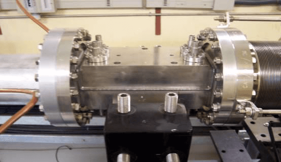
Figure 12 : Stripline
Principle of operation
Stripline has four strips (conductors) running along the axes of beam, parallel to the vacuum chamber wall, placed symmetrically in the cross section of the beam duct. The length of the strip is usually longer than the characteristic bunch length. The strip forms a transmission line structure with the wall of the vacuum chamber. The electromagnetic field of the beam induces signal on the strip line. The amplitude of signal induced in the strip (conductor) is a function of its solid angle subtended on the beam and distance of the conductor from the beam. The width of the strip and its spacing from the vacuum chamber wall is so decided that its characteristic impedance should match with impedance of coaxial transmission line, which is generally 50O±2%. The length of stripline is chosen to be equal to quarter wavelength of fundamental RF frequency to get the maximum sensitivity. Two ends of the stripline are taken out of the chamber by using vacuum feed through connectors. These are called upstream and downstream ports respectively with reference to the beam direction. For taking the signal from the stripline, the downstream port is terminated in to characteristic impedance and signal is taken from the upstream port. To use it as kicker, RF power is fed in anti-phase to the downstream ports of a pair of striplines located opposite to each other. The Lorentz force acting on the electron bunch due to the electromagnetic field created by the striplines gives a transverse kick to the beam and the beam starts oscillating. The oscillation frequency is analyzed by a spectrum analyzer and the tune value is obtained.
Construction details
Strips are made up of OFHC copper because of its high electrical conductivity. The containment, which supports the strips, is made up of SS 316 L and it is made in two halves to facilitate the simple machining of complex cross section. Design for the vacuum containment is such that it accommodates the copper strips with minimum discontinuities in cross-section of beam duct, which is necessary to minimize the beam coupling impedance. Effectively 142 mm long, 13.5 mm width, and 1 mm thick copper strips are connected at both ends, to the BNC feed-through. The BNC connectors are welded to CF 34 flange to form vacuum compatible joint. Vacuum compatible machinable ceramic (MACOR) is used as insulating material between copper strips and the body of stripline. As the stripline is part of storage ring, it is ultra-high vacuum compatible. Diamond seal gaskets and DS flanges are used to have ultra-high vacuum compatible seal.
Tune measurement system
Tune measurement system will be controlled by the control system. It is based on continuous harmonic excitation
method. The measurement system employs a spectrum analyzer equipped with a tracking generator. The spectrum analyzer is controlled by a PC through GPIB bus. A strip line kicker is used to excite the beam. The tracking generator RF output is given to a remotely controlled x/z selector, which incorporates RF switches. Depending on the user selection, either horizontal or vertical tune measurement function is selected. The RF signal is then fed to a network of hybrid junction and 180° two-way power dividers to produce four output signals. The phase relationship of these signals is such that when applied to the strip-line, the beam gets a kick in the desired plane (horizontal or vertical). The RF signals are amplified by 50-watt RF power amplifiers before driving the strip line kicker. Another strip-line in the storage ring is used as beam position monitor to observe the betatron oscillation. The four strip-line outputs are combined in a network of hybrid junctions to produce real-time x and z delta signals proportional to the beam position in horizontal and vertical plane. Low loss, phase matched coaxial cables are used for this purpose. After passing through the x/z selector, the signal is applied to the RF input of the spectrum analyzer. During the frequency sweeping, when the excitation frequency passes through the betatron side band, amplitude of the oscillation grows and it is displayed as a peak on the spectrum analyzer. From the frequency of the peak, tune value is calculated and displayed on the monitor.
5) Scraper
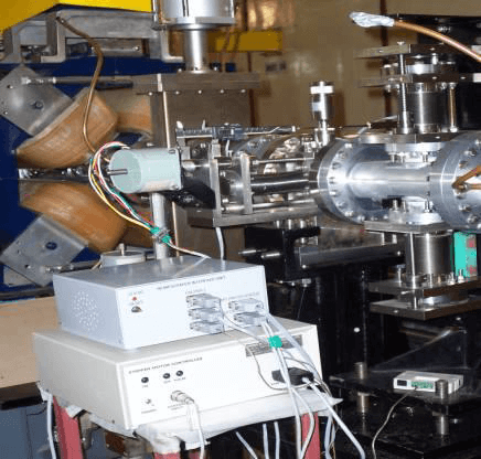
Figure 13 : Scraper
Scraper is a destructive type of beam diagnostic device, which is used to locate the center of beam in beam duct and to infer about the transverse limit of the beam. It can also be used to dump the residual beam. Horizontal and vertical scrapers are used for the two axes respectively.
Principle of operation
Scraper is essentially having single or a pair of blades, which move in to the beam to cut the beam, transversely. Beam current, which is measured in the down stream, as a function of blade position, is processed to have the position of center of the beam in transverse plane.
Construction details
Blades of the scraper are made of SS 316L, which are inserted into the beam with the help of stepper motor operated lead screw mechanism. The requirement of precise increment and position of the blade restrict the use of other mechanism such as pneumatic actuator. To sense the position and movement of the blade, digital vernier is used. Output of sensors is used as feedback for post-processing. To ensure linear motion of the blade, cylindrical guides are used. To convert rotary motion from stepper motor to linear motion of scraper blades, ball screws are used. Ball screws are antifriction type to reduce the friction and hence to reduce the torque required. For better precision, anti-backlash mechanism is also incorporated.
The edge welded bellows are used to accommodate the to and fro motion across the vacuum - air interface. For lower spring rate and better movement the edge welded bellows are selected. Bellows are made-up of SS 316L.The body of the scraper is made up of Al 5083. Section of drift tube (straight section) is used as body for scraper to match the inner profile of beam duct. As the beam scraper is part of storage ring it’s design should be UHV compatible. Various UHV compatible demountable joints are used for easier assembly and maintenance. Diamond section gaskets are used for UHV sealing. Fig.6 shows the assembly drawing of vertical scraper.
Electronics To control the operation of the scraper, a microcontroller based intelligent local controller unit has been developed. The main function of the controller is to control the movement of the stepper motors, read position of the blades from the digital calipers and read the status of the limit switches. To control the three stepper motors, the microcontroller sends the direction control and pulses to the stepper motor drivers. These signals are isolated from the driver circuit by using optocouplers. The stepper motor RPM can be varied by changing the pulse rate. For blade position feedback, Mitutoyo make digital calipers with an interfacing port have been used. Limit switch status is monitored continuously during the blade movement. The motor is stopped if the blade reaches its extreme position. The interface unit is connected to the host computer on RS-485 serial link. This allows all the three units to be connected on a common bus.
Operation The scraper is operated remotely from the control room. Depending on the user requirement, control system sends command to the controller to move the blades by the required displacement. The information about the blade position is displayed on the console. DCCT current is recorded as a function of the blade position and plotted on the console.
6)Wall current monitor
Wall current monitor (WCM) is used in TL-3 for observing the bunch signal. Operator gets the information about the number and amplitude of bunches passing through the monitor. The signal from the WCM installed at the beginning of transfer line gives information about the extracted bunches from the booster. Beam passage through the transfer line is optimized by monitoring bunch signals from wall current monitors located at various points along TL-3.
Principle of operation:
The beam current flowing in the beam pipe (vacuum chamber) is accompanied by an equal “wall current” (image current) on the inner surface of the beam pipe, flowing in opposite direction. The origin of wall current can be explained as follows. The electric and magnetic fields due to the beam are properly thought of as electromagnetic waves propagating out from the beam. At low frequencies, the magnetic component of the wave penetrates the metallic walls of the beam pipe. Hence, the dc magnetic field exists external to the beam pipe and can be measured, for example, with a second harmonic type dc transformer. At higher frequencies, the wave is attenuated as it propagates through the conducting beam pipe due to skin effect. At high enough frequencies, where the skin depth is a fraction of the wall thickness, the attenuation is effectively complete. No high frequency field appears external to the beam pipe. For this to happen, the fields due to beam current must be exactly cancelled by equal and opposite fields due to some other current distribution. Since the beam fields appear within the beam pipe, but not outside of it, current in the wall of the tube must generate the cancelling fields, which is the wall current.
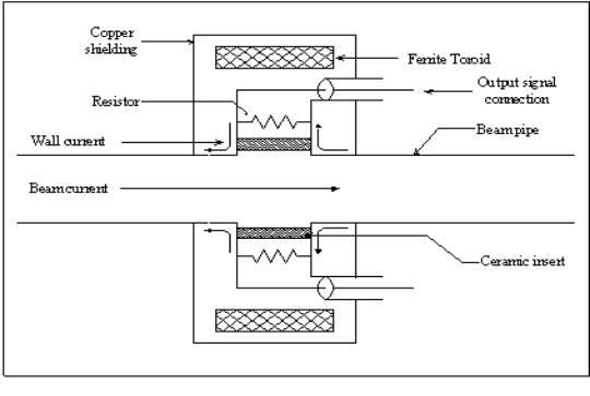
Figure 14: Wall current monitor
A schematic of wall current monitor is shown in fig. 7. An electrical break is imposed in the wall current by introduction of ceramic ring in the beam pipe and this current is diverted to flow through the resistors connected across the ceramic ring. The voltage developed across the resistor due to the flow of wall current is taken out by a coaxial cable for further processing and observation. To avoid perturbation through circumferential modes, resistors are connected at several points symmetrically around the circumference of the beam pipe cross section. Signals from these resistors can be summed together to provide a position insensitive beam current signal. When the beam is not at the center of the beam pipe, the wall current will be unequally distributed around the circumference of the chamber. In this case, signals from resistors can be processed separately to get beam position by applying suitable algorithm. Ferrite cores surround these resistors in order to reduce part of image current flowing through the metal housing which encloses the wall current monitor. Use of ferrite core also reduces the possibility of external noise currents affecting the output of wall current monitor. This monitor has advantage of good high frequency response.
Operation
Wall current monitor is a passive device. Its signal will be continuously available in the control room for observing on a digital storage oscilloscope.
7) Sighting Beam Line
Sighting Beam Line (SBL) is a Synchrotron radiation based diagnostic beamline to monitor the beam parameters specially during commissioning of the Indus-2 machine, when beam current is low and other monitors in the ring are not much effective. Machine operators can visually observe the synchrotron radiation. SBL has a front end consisting of slit, radiation absorber, all metal pneumatic valve, and fast shutter. It has Mirror box fitted with CCD camera to measure the beam size, position along with visual observation. Staggered blade pair-monitor to monitor precise vertical beam position shall also be introduced at a later stage. A schematic diagram of the SBL is shown in fig. 8.
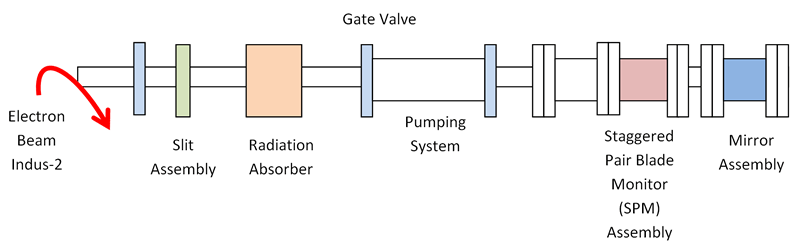
Figure 15 : Schematic of sighting diagnostics beamline for Indus2 Figure16

Figure16 : Sighting diagnostics beamline (BL-27) installed in Indus2
8)Septum Hole Monitor
Beam injection into Indus-2 is achieved with the help of two septum magnets, a thick septum followed by a thin septum. The areas external to the beam entrance apertures of these two septa are covered with fluorescent material, viewed by video cameras. This monitoring arrangement helps the machine operator to visually observe any beam or part of beam which misses its desired trajectory passing through the aperture.
9) X-ray Diagnostic Beamline (BL-24) at Indus-2
Synchrotron radiation (SR) based beam diagnostics is used for the measurement of beam parameters without any perturbations to the beam. We have designed, developed and commissioned x-ray diagnostic beam line (X-DBL) at the Indus-2. It is based on the pinhole array imaging (8-18 keV) to measure transverse beam parameters such as beam size, beam divergence, beam emittance, beam instability etc. Its remote operation control and results of online measured data are available in the Indus control room. The knowledge of these parameters helps in stable and smooth operation of the Indus-2 SRS. It helps in exploring various transverse instabilities present at different operating conditions of machine. Beamline details are provided at the following link:
https://www.rrcat.gov.in/technology/accel/srul/beamlines/xray_diag_beam.html
10)Visible Diagnostic Beamline (BL-23) at Indus-2
Beam line BL-23 is designed, developed and commissioned as a visible diagnostics beam line in Indus-2 storage ring. Its source point is at 5℃ port of bending magnet (DP-10) in Indus-2. A water cooled copper mirror at 5.5 m from SR source point acts as a primary pick-off mirror. It intercepts only lower half (visible part) of the dipole light with total horizontal angular acceptance of 5 mrad. The extracted visible light follows reflective and refractive optics, and focused on optical table in the dark room outside the shielding wall of Indus-2. Final measuring point in dark room is at a distance of ~20 m from source point. Instrumentation on optical table includes beam profiler, dual sweep synchroscan streak camera, position sensitive detector PSD, fast photo receiver etc. V-DBL is used to observe and study longitudinal beam parameters like bunch length, bunch separation, bunch filling pattern, longitudinal beam instability etc. Beamline details are provided at the following link:
https://www.rrcat.gov.in/technology/accel/srul/beamlines/visible_diag_beam.html
Table 1: Beam diagnostic devices in Indus-2
| S. No.
| Name of diagnostic device
| Total quantity (Nos.)
| Location/distribution
| Function
| Remarks
|
| 1
| Beam Position Indicator
| 56
| 7 Nos. in each cell
| Measurement of beam position, COD
| Individual type: 40 Nos Integrated type: 16 Nos
|
| 2
| Beam profile Monitor
| 19
| a) TL-3: 8 Nos. b) Storage ring: SS-1: 2 Nos. SS2 to SS8 : 1 No in each section LS-1: 1 No. Septum chamber: 1
| Visual observation of beam profile and position
| Fluorescent material: Cr doped Al2O3
|
| 3
| DCCT
| 1
| LS-7
| Measurement of average beam current
|
|
| 4
| Stripline
| 6
| 1 No. Each in SS-1, SS-2, SS-3, SS-4, LS-6, LS-7
| Tune measurement Beam signal observation Transverse feedback for instability correction
| Tune measurement: SS-1 : kicker SS-2 :Beam position monitor.
|
| 5
| Scraper
| 2 H + 1 V
| LS-7: 1 H + 1 V SS-5: 1 H
| To locate the center of beam in beam duct, dumping of the residual beam.
| H- Horizontal scraper V- Vertical scraper
|
| 6
| Wall Current Monitor
| 4
| TL-3
| Observation of bunch signal
|
|
| 7
| Sighting Beam Line
| 1
| BL-27
| Observation of synchrotron light during machine commissioning
|
|
| 8
| Septum Hole Monitors
| 2
| Thick and thin septum
| Visual observation of the injected beam at the septum mouth.
| Septum hole viewed with a CCD camera
|
| 9
| Visible Diagnostics Beamline
| 01
| BL-23 Indus2
| To measure bunch length and longitudinal dynamics of Indus-2 electron beam.
|
|
| 10
| X-ray Diagnostics Beamline
| 2
| BL-24 Indus2
| To measure Beam size, beam emittance, beam profile etc. of Indus-2 electron beam.
|
|
|
|
|
11) Transverse bunch by bunch feedback system
In a storage ring, at high beam currents, transverse instabilities of the beam adversely affect the machine performance. Transverse instabilities may result in the saturation in beam accumulation, partial or complete beam loss and increase in the transverse beam size etc. To cure these instabilities, transverse bunch by bunch feedback system is installed and commissioned in Indus-2. Two feedback loops one for horizontal plane and another for vertical plane have been installed and these are working since 2014. Based on the operating conditions of Indus-2 and changes in machine parameters, the feedback system parameters like gain, filter coefficient and phase were optimized for faithful operation of the feedback system.
The schematic diagram of the transverse bunch by bunch feedback system is shown in figure 1. One of the beam position monitor (BPM) has been selected to pick up the beam oscillation. The outputs of the BPM are fed to an RF hybrid unit to produces the real time horizontal, vertical and longitudinal signals which are proportional to the horizontal, vertical and longitudinal oscillations at the BPM.
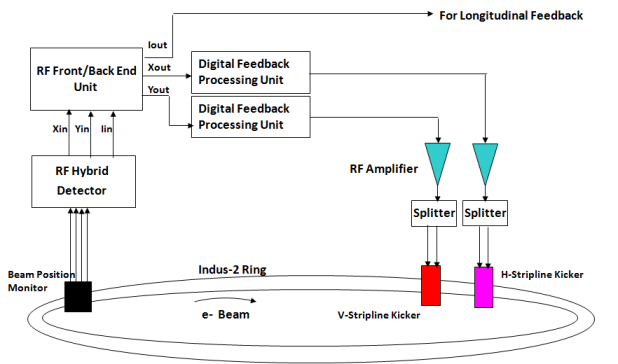
Figure-17: Schematic diagram of transverse bunch by bunch feedback system
The output signals of RF hybrid unit are fed to the RF front-end unitfor demodulation of these signals and produces base band signals with bandwidth of ~253 MHz. The Feedback processor units are used to generate the kick signals proportional to measured instability signal. The kick signal is amplified using broadband RF amplifiers and split into 0° and 180° phase signal using high power splitter. The output of splitter is fed to the stripline for applying the correction.
The MATLAB based GUI of the transverse bunch by bunch feedback system has been developed and snapshot of it is shown in figure 2. The software interfaces with the bunch by bunch front end and processing units for automatic adjustment of phase and amplitude.
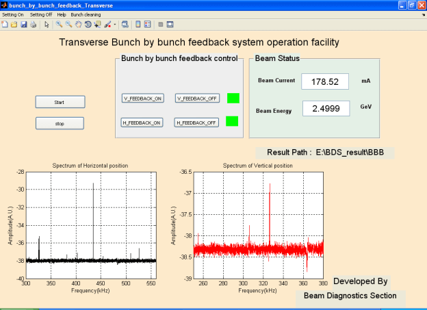
Figure 18: Snapshot of the GUI of transverse bunch by bunch feedback system
Software acquires the bunch by bunch data and applies signal processing technique to improve the signal to noise ratio of the acquired data for beam parameter measurement. Software provides a user interface for single button control for feedback operation and also log the data like feedback status, beam current, beam energy etc.
12) Diagnostics for H- Linac
Faraday Cup:-
Faraday cup is used to measure the bunch- charge, temporal profile and bunch length It is very useful during commissioning and characterization.Two types Faraday cups were designed, one with 50 mm aperture for initial characterization of H- ion beam from ion source for initial uncorrected comparatively large beam size and another with 20 mm aperture for corrected and controlled beam after the ion source.Thermal load, high-vacuum compatible electrical isolation and structural integrity were the major design concern for FC.
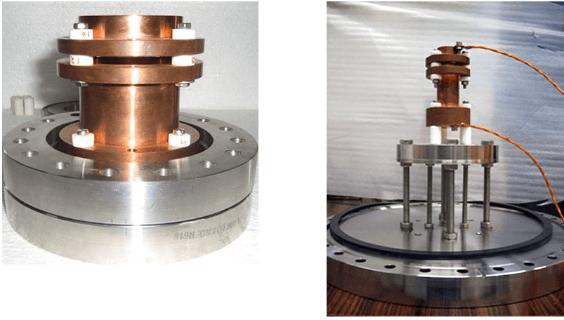
Figure 19(a) 50 mm aperture Faraday cup assembly Figure 19(b) 20 mm aperture Faraday cup assembly
Double slit type Emittance monitor:-
Double slit type emittance monitor has two slits: primary slit for position and collector slit for angular distribution. Primary and secondary slits are made of 1 mm thick tungsten sheet masked by 12 mm OFE copper plate, and have opening of 200 μm to allow beam to pass through. Primary slit has stroke of 120 mm, scans the beam transverse to beam axis with ±20 μm positioning accuracy and 2 μm resolution. Collector slit scans through the ± 25 mm about the position of primary slit and have insulated collector plate which collects H-ions to give the angular distribution about the position of primary slit.Indigenously developed low current measuring device has been used to measure the current on collector plate.
Figure 20(b) Phase-space distribution at H- ion source Figure 20(b) Phase-space distribution at H- ion source
LEBT Diagnostic chamber:-
Diagnostic Chamber is a multi- port vacuum containment for housing the various diagnostic devices for LEBT of H-Linac. Space limitation and number of diagnostic devices required in LEBT forced to design, compact, UHV compatible multi- port chamber Available design codes does not recommend such close port openings, a detailed simulation based structural analysis was carried out confirm its structural integrity. The chamber has 12 different size ports to accommodate slit and harp type emittance monitor, wire scanner, Faraday Cup, and there are ports for TMP, SIP and BA gauge.
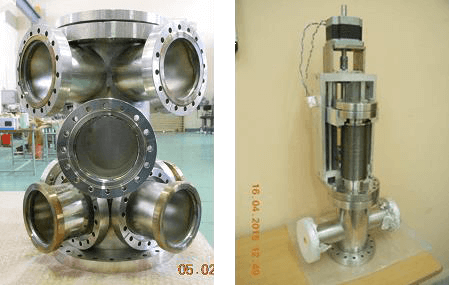
Figure 21(a) Multi-port diagnostic chamber for LEBT Figure 21(b) Modular Actuation Mechanism for Diagnostic devices
13) Setup for Calibration of Beam Position Indicators of Indus-2
Beam positions Indicators (BPI) are non-interceptive diagnostics devices which are used for finding the position of electron beam in accelerators. Upgraded BPIs for Indus-2 has been designed for higher sensitivity and more precise beam position measurement. These beam position indicators are calibrated on a test bench before installing in Indus-2 ring. The aim of calibration is to find the sensitivity and a suitable mapping function to convert induced voltage signals into position information. The position information from these BPIs is used for correction of closed orbit distortion and maintaining orbit within few tens of microns. An upgraded calibration system has been developed indigenously.
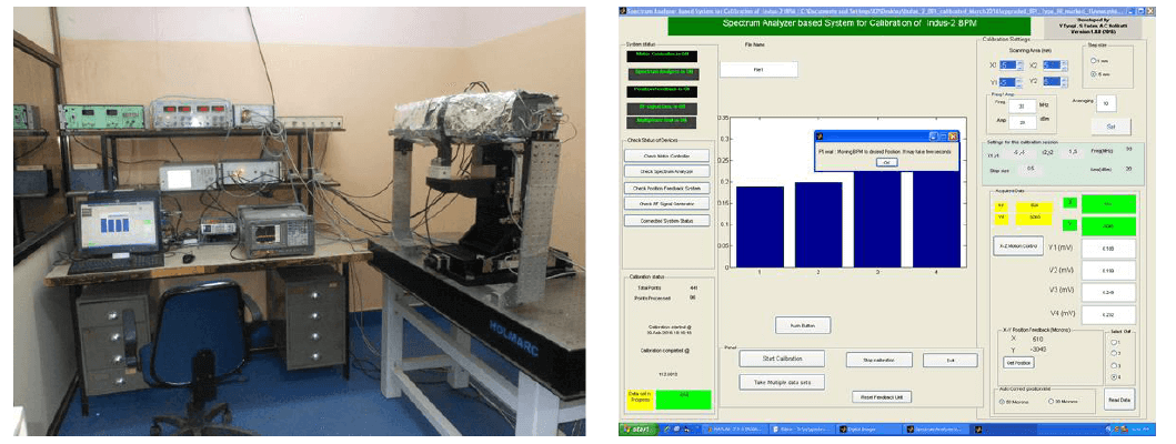
Figure 22: Upgraded System and Software GUI for Calibration of Beam Position Indicators
|


