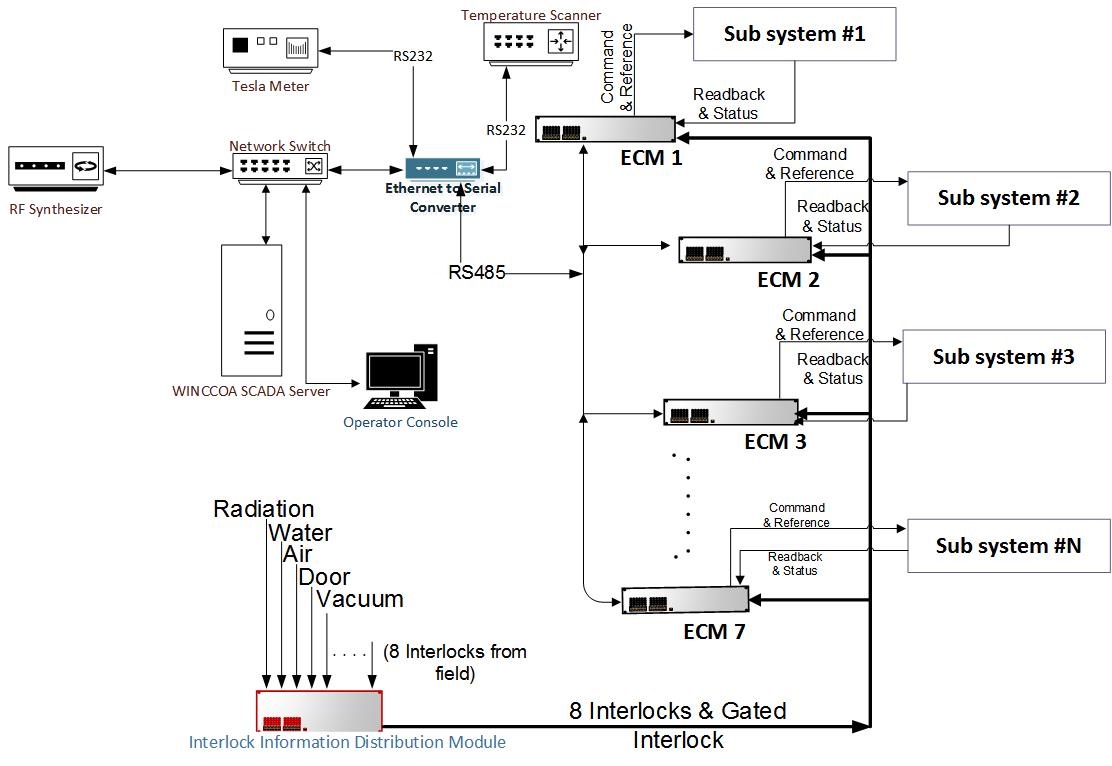
The control system is based on a distributed supervisory control system scheme having two-layer hardware architecture. In this scheme each of the subsystems of the Microtron is supervised by dedicated controllers named as Equipment Control Modules (ECMs). Following features of the distributed control system architecture or scheme were the motivation behind implementation of control system based on this scheme.
Reduction in cable load due to ECM sitting in the vicinity of the subsystems.
Reduction in the long interface cables has reduced the possibility of EMI issues.
Maintaining isolation in the interfaces is rather easy.
All the ECMs are identical in design & functionality and hence approach is modular.
Due to the presence of uniform interface and modularity, maintenance is easy.
High data rate communication over RS485 can help increase parameters update rate.
The ECMs provide all the required basic functionalities and some special functions like cycling and degaussing of magnets. The logic of the ECMs is implemented in Field Programmable Gate Arrays (FPGA) and few support ICs. This constitutes front end instrumentation or Equipment Interface (EI)/ Equipment Control (EC) layer or layer-2.
The interlock information from all over the field is collected in a central Interlock Distribution Module (IDM), which is multiplied for sending to each ECM over a separate 24 V line. Each ECM gets aggregate interlock infromation from such 24 V line, combines it with the local interlock information and takes appropriate actions on the subsystems if any interlock fails.
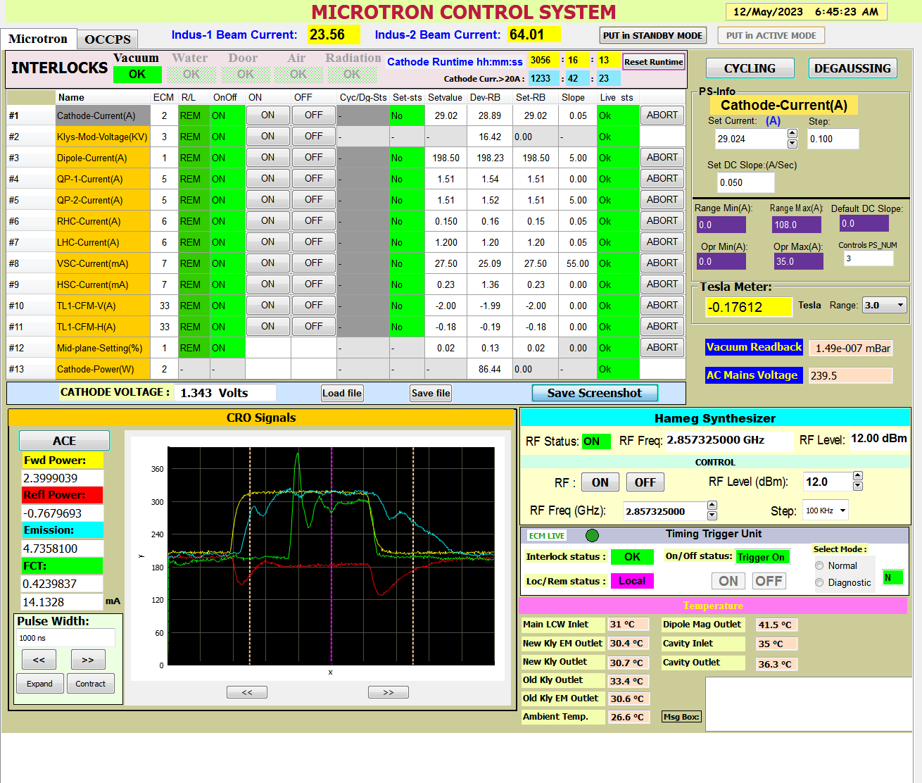
All the ECMs and IDM communicate with the server program and GUI at operators’ console through a custom protocol over an RS-485 serial bus. This is the User Interface (UI) layer or Layer 1. SCADA is used at Layer 1 as it is used for Indus-2 control system. The scheme of the Microtron Control System and a GUI panel of user interface are shown in figure 1 & 2 below.
Figure 1:
Distributed Architecture of Microtron Control System [Full Size Image]
Interlock system in new Microtron control system consists of interlocks like water-flow, air-flow, area door-closed, pressure inside the Microtron and radiation within limit. For safety of personnel and the machine it is required that the machine (the affected subsystem and/or Microtron) operation is possible only when all the interlocks are healthy or in good condition. If any of the interlocks fails, the machine is put off automatically. The interlock system in the new control system is a separate layer of hardware. It is implemented in modular fashion. It consists of central Interlock Distribution Module (IDM), interlock receivers in each ECM and the interlock bus. The IDM receives all the interlock signals generated at various sensors and instruments located in the Microtron area, isolates them and drives the interlock line to every ECM in the form of contacts powered with 24 V. The IDM has provision for eight interlock input signals as passive contacts. It is a relay based module that generates a master interlock for the trigger generator also. At each ECM, the interlock line is isolated and the status is read by the logic implemented in FPGA. On interlock failure, each ECM takes appropriate actions on the connected subsystem. These actions are governed by equations implemented locally in the hardware of respective interlock receiver card in the ECM. The whole interlock chain is implemented in hardwired logic made using relays. All unused interlock inputs are to be made active for the IDM to work properly. These extra inputs can be used in case if any such requirement arises in future.
Controls for Combined Function Magnet Power Supplies in Transport Line-1
Injection of electron beam from Transport Line-1 (TL-1) into Booster Ring (BR) is dependent of the position of the
beam in the TL-1 and its entry angle at the mouth of injection septum magnet of BR. The trajectory of the beam inside
TL-1 is decided by the optics fixed by various magnets on the TL-1. Study of the beam current trajectory in TL-1 is
also being done to optimize current in BR. This requires additional handles to steer the electron beam in TL-1.
Thus, a Combined Function (CF) magnet is installed at beginning of TL-1. The name "Combined Function Magnet" is
given, for it can steer electron beam in both the horizontal and vertical direction. The magnet coils are excited
by two independent power supplies. The Microtron control system is upgraded to include controls of both the CF power supplies.
Controls of Cycling & Degaussing of Microtron Dipole Magnet
Special control functionalities like cycling and degaussing of magnets are also needed. Cycling is required to set the
repeatable uniform magnetic field in the magnet pole gaps. The stray or remnant magnetic field in the pole gaps of these
magnets may cause an undesired deflection of the beam in TL-1 when the magnets are kept off. Thus it is necessary to bring
the remnant magnetic field to near zero before these magnets are switched off. This requires cycling of magnetic field
of the magnet around "zero" in a converging fashion. This is achieved by varying the current in the magnet coils from
zero to positive peak with a predefined rate, staying there for a while, bringing to negative peak with the same rate,
staying at the negative peak and then taking it back to zero with the same slope. Such cycles are repeated with
successively reducing positive and negative peaks. This shrinks the B-H loop and converges the remnant field to near zero.
This process of bringing the remnant field to near zero is referred to as "degaussing".
Control system software is upgraded with inclusion of control and monitoring functions for the two supplies and also
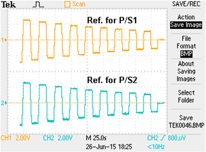
special functions like cycling and degaussing. Two types of degaussing procedures are implemented. One is "symmetric
degaussing" as shown in figure 3 in which the positive and negative peaks of a period of cycle are equal and the
next cycle has both reduced by a fraction of the previous peak value. This goes on till the peaks reduce to a permissible
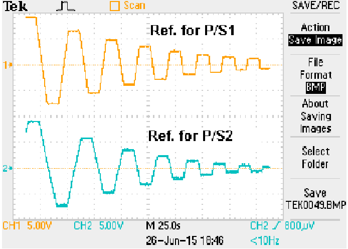
value near zero. In the "asymmetric degaussing", shown in figure 4, the very next peak (negative or positive) is
reduced by a fraction of the previous peak. All these Control software modules are developed for the VME CPU.
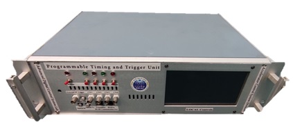
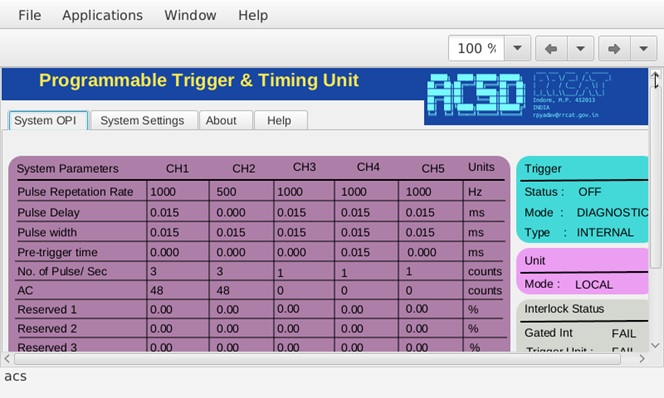
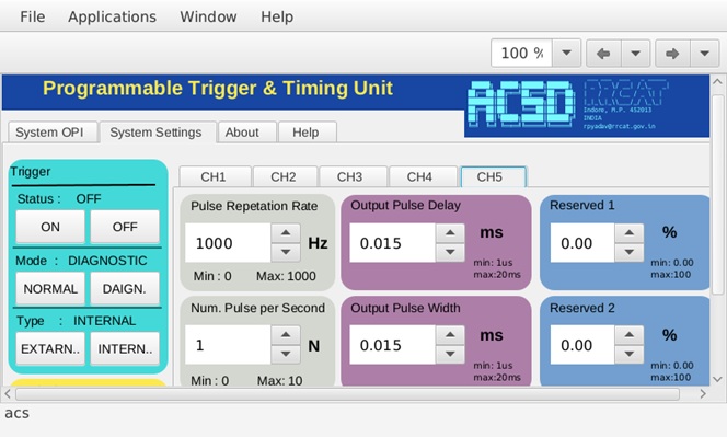
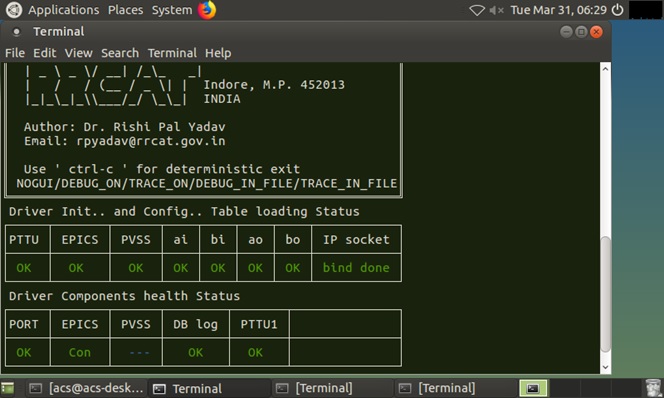
Programmable Timing and Trigger Unit (PTTU) is one of the main subsystem of any particle accelerator facility which is designed and developed at RRCAT. Its main role is to generate and provide repetitive timing andsynchronization signals to other sub-systems such as modulator power supply, magnets power supplies, etc. so that e-bunches/beam can be formed and stored in the storage ring of the facility. From system operation point, the triggers are used with configurable parameter such as Pulse Repetition Rate (PRR), Delayed Pulses, No. of pulses within repetition time, Pre-Trigger time delay, etc.The unit can be controlled remotely or locally. To operate it from remote, it must be ensured that it must communicate over the channel and can be integrate with control system of other sub-systems.For interfacing with various other sub-system of the facility, the triggers are generated with TTL standard as well as optically. RS85 serial interface, Network interface and custom communication protocol is also implemented in the design. For local controls, Embedded system based Touch Panel is provided. The system is designed using open source SCADA i.e. EPICS and CSS is used for GUI development. The complete development is on LINUX environment. The unit not only to generate output pulses but it also takes suitable action for human safety. It incorporates several interlocks such as door, air, water, radiation, vacuum, search and other. A suitable action is taken by the unit on failure of any of the interlock. The action will be fast to protect any human life and machine safety both.
Salient features of the Unit are:
Advanced Technology like FPGA and SBC are used.
5 Independently Programmable Output Triggers [4 are TTL (50? drive) and 1 optical output].
PRR can be configurable from 1Hz to 1 kHz.
Inter-pulse delays can be adjusted in few tens of nanosecond range.
Touch Screen local settings from more advanced and better user experience.
1G Ethernet connectivity and 1Mbps RS485 interface.
RS232 port for diagnostics and optical fiber communication port.
LED indications for system status and faults.
Operation Modes: Trigger ON / OFF, Normal / Diagnostics, Local / Remote.
Indigenously designed and developed to encourage self-dependent aim.
Reconfigurable and reusable hardware means same design can be used for multiple purposes.
Open source tools for software and embedded development.