| Controls, Diagnostics and Beamline Instrumentation Division |
| Timing Control System (TCS) for Indus-2 |
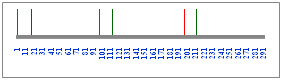
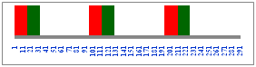
Time synchronization of the pulsed power supplies & magnets used for providing fast kicks to the electron beam for functions like injection and extraction is very critical in accelerators. Programmable trigger pulse generator boards provide the necessary triggers for these pulsed magnets. The RF frequency of operation in Indus-2 is higher and different than that of Booster (BR). Hence a coincidence frequency is generated and all triggers are locked to this frequency. Extraction of two bunches from BR and their injection into specific bucket(s) out of 291 buckets in Indus-2 requires very tight synchronization of timings of the pulsed devices. On the top of that there exists requirement of different filling modes in the Indus-2 namely Single bunch filling, Three Symmetric bunch filling and Single train, Two trains (Fig.1), Three trains, Variable gap-width, continuous filling etc. to fill the buckets without overlapping. All these complexities are dealt by the Timing Control System. RF frequency of Indus-2 is 505.8 MHz, which poses very tight requirements on the trigger and timing part of the control system. Requirement of maximum jitter of the order of 1 nsec between the trigger signals of extraction kicker and four Injection Kicker power supplies is to be met. To generate accurate time delays with jitters within the specified tolerance, multi-channel coarse and fine delay generator cards were developed.
To support required filling modes coincidence generator card was developed using ECLin PS family integrated circuits operating at 505.8 MHz. All the delay generator boards are Spartan-3 FPGA based VME (A24:D16) to deliver trigger with 1 ns resolution and channel-to-channel jitter < 1 ns.
In addition, the TCS also monitors and controls the pulsed, high peak current power supplies for these fast pulsed magnets.
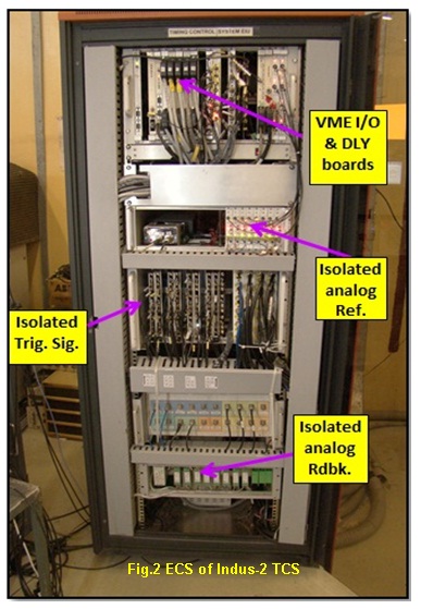
Signals are interfaced with pulsed devices with channel-to-channel isolation implemented by opto-coupler and fibre optic based signal interfacing. Over the time, TCS is updated /modified to meet new requirement and betterment. Equipment Control Station (ECS) of Indus-2 TCS and the GUI panel are shown in Fig.2 and Fig.3 respectively.
|
 |
 |
| Figure1:Trigger generation & Indus-2 bucket fillings in Two trains mode[Full Size Image] |
Figure2: Control rack of Indus-2 Timing system[Full Size Image] |
|
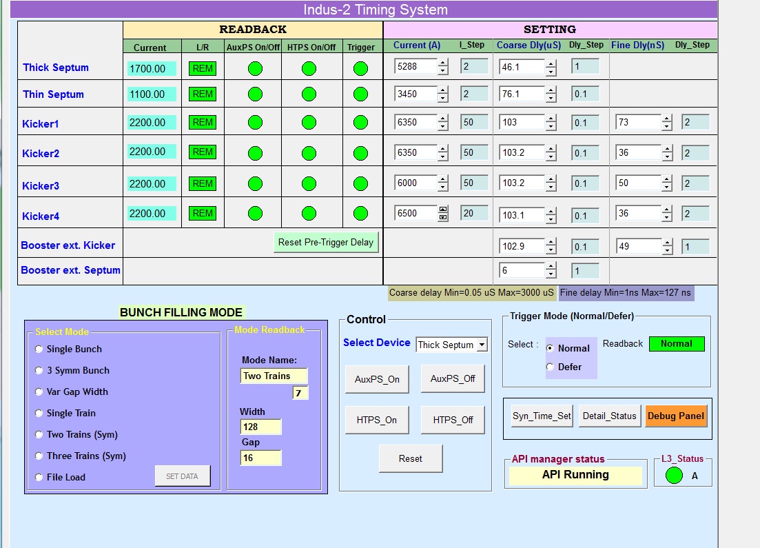 |
| Figure3: Screenshot of Timing Control System Software. |
|
| New Bunch Filling Patterns for Indus-2 Ring |
|
The electron bunch filling pattern in Indus-2 ring is controlled by the VME based Timing Control System. The algorithm is implemented
in an OS-9 program running on Motorola 68K CPU board. Indus-2 ring has a total of 291 positions in which bunches can be filled. These
are called as Buckets which are about 2 nsec apart. Out of three bunches revolving in booster two bunches get extracted and filled in
Indus-2. These two bunches are separated by a distance corresponding to 16 buckets of Indus-2. So if the first bunch is filled at bucket-1
then the second will get filled at bucket-17. The second bunch can be referred as 'Concomitant bunch'.
A sequence of consecutive bunches is called a 'Train'. A train contains main as well as concomitant bunches but without overlapping i.e. a
main and a concomitant bunch will not be filled at the same given bucket in a train. Initially there were three bunch filling patterns available
to the operator. Recently five more bunch filling patterns have been incorporated in the system.These are required for ion trapping studies and
for high current injection trials. This article briefly describes all the eight patterns.
1. Single bunch
In this mode the operator selects a single bunch number (1 to 291) that has to be filled. Along with the main bunch (red) the concomitant
bunch (green) also gets filled.
2. Three symmetric bunch
In this mode bunches at bucket location 1, 97 and 194 are filled along with their corresponding concomitant bunches.
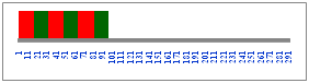
3. Multiple bunch
In this mode the operator selects the start and end bucket numbers (1 to 291). The buckets between these two values are filled repeatedly
with overlapping (black) of main bunches and concomitant bunches.
4. Variable width and gap between the trains
In this mode the operator selects the width of the train (1 to 16) and gap between the trains (0-277). The buckets are then filled without
overlapping and the number of trains gets decided as per the amount of gap provided.
5. Continuous filling without overlapping
In this mode the buckets from 1 to 288 are filled without any overlap of main and concomitant bunch.
6. Single train
In this mode a single train is filled without overlapping starting from bucket-1. The operator can choose the width of the train from the
values 32, 64, 96, 128, 160, 192, 224, 256 and 288.
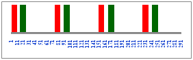
7. Two trains
In this mode two trains are filledwithout overlapping. Operator can choose width of the train as 32, 64, 96 or 128. First train starts at
bucket-1 and starting bucket of second train can be selected between 130 and 160.
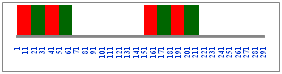
8. Three trains
In this mode three trains are filled without overlapping starting at bucket 1, 97 and 194. The operator can choose the width of the train as
either 32 or 64.
|
|
|
Pinger Magnet Control:
Two more pulsed magnets are introduced in Indus-2 ring for performing beam dynamics study by giving kick to the stored electron beam at 2.5 GeV in horizontal and vertical planes. They are named as Horizontal and vertical Pinger magnets. These will be remotely operated. Pinger magnets require similar control system in addition to stringent timing trigger requirement. Hence Indus-2 TCS is augmented to accommodate new hardware for interfacing various signals to monitor, control and generates stringent timing signal which are synchronised to Indus-2 Revolution clock with jitter < 150 ps. Software is updated to implement new requirement. GUI panel is shown in Fig. 12. Control system is commissioned and running successfully for remote operation of Pinger magnet for different beam physics experiment.
 |
| Figure12:GUI Panel for Pinger magnet operation |
|
|