| Controls, Diagnostics and Beamline Instrumentation Division |
| |
| Architecture of Indus-2 SRS Control System |
| Overview |
Any large facility like Indus-2 involves various sub-systems, which are quite extensive in themselves. These sub systems are working closely together, towards achieving the desired goals and performance. The control system has the prime task of facilitating the monitoring, supervision and control of all the important parameters of the machine and various sub-systems. To achieve this, it has to interface and interact with various sub-systems at different levels of hardware and software. Any control system itself consists of various modules in hardware and software, each performing a particular task. Indus-2 control system also consists of various modules and layers in hardware and software and also data communication links. The control system follows a layered architecture that highlights the approach followed in designing the system. |
| |
| Design Philosophy |
The control system is based on master slave architecture and it enables functional and physical separation and placement of hardware and software modules across the entire gamut of control system components. Reliable, fast network & communication support is the backbone over which various hardware and software components talk to each other. The distributed system approach is followed which helps to shorten the cable lengths, reduces cable concentration at any one place and also minimises the possibility of signal interference. Only essential communication and minimum instrument cables are brought inside the control room. Operation is done with software panels and minimum number of physical switches and knobs. Signals are concentrated, multiplexed and pre-processed in the field units as far as possible. Standard hardware, connectors, signal levels, control modes etc. are used across sub-systems. |
| |
| Architecture |
Based on the above design philosophy, Indus-2 control system uses a distributed architecture with use of modular systems at various levels. The control system is divided into a number of intelligent subsystems each of which autonomously controls a specific subsystem such as magnet power supplies, RF, vacuum, Beam diagnostics, etc. These control room computers can share the data across the network. Identical hardware and software modules are used to perform tasks of similar nature.
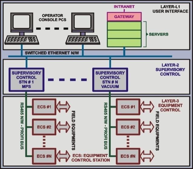
The control system is distributed over three layers namely User Interface layer (UI), Supervisory Control layer (SC) and Equipment Control (EC) layer.
The upper layer known as User Interface Layer consists of computers for functions like operator consoles, file servers, data base servers, central alarm handling, software development, auxiliary system monitoring etc. These computers are connected over switched Ethernet LAN and possess high computing power and good graphics capability to handle effective data presentation. The computers designated as operator consoles allow the operator to run and supervise several control and monitoring processes simultaneously by means of windowing tools.
The second layer is the Supervisory control layer that consists of Supervisory Controllers (SC) performing the task of supervisory control and data acquisition. Each of these computers supervise the operation of a particular subsystem through a set of equipment controllers linked to them. SCs receive commands and set values from the operator console over network. SC is connected downward to the EC layer by Fieldbus.
|
 |
| |
Figure1: Indus-2 Control System Architecture |
The third layer which is closest to the field equipments consists of Equipment Controllers (EC). These microprocessor-based intelligent controllers are the workhorse of the control system. The ECs of a particular sub-system communicate with the SC dedicated for that particular subsystem. Most equipments in the field are interfaced to control system through ECs. Each EC can monitor and control the equipments interfaced to it, according to the tasks assigned by the SC. It continuously monitors the status of the equipments and reads various parameters for their current values and sends this information to the concerned SC on request.
This distributed and modular architecture makes the system flexible to accommodate necessary upgradation that may be needed in future. The use of distributed, intelligent modules also helps to improve the overall system response.
In addition, a number of computers are connected on the same network to display the status and other information as and when required.
The second layer is the Supervisory control layer that consists of Supervisory Controllers (SC) performing the task of supervisory control and data acquisition. These computers are responsible for the proper operation of a single subsystem. One SC is assigned to one subsystem. SCs receive commands and set values from the operator console over network. SC is connected downward to the EC layer by Fieldbus.
The third layer consists of Equipment Controllers (EC). These microprocessor-based intelligent units form the backbone of the control system. These ECs will be connected to SC, dedicated to a particular subsystem of the machine. All equipments in the field are interfaced to control system by ECs. Each EC controls and monitors the equipment it is interfaced with, according to the tasks assigned by the SC to which it is connected upwards. It continuously monitors the status of the equipment and reads various parameters for their current values and sends this information to concerned SC on request.
This distributed and modular architecture makes the system flexible to accommodate necessary upgradation that may be needed in future. The use of distributed, intelligent modules also helps to improve the overall system response. |
| Hardware |
| According to architecture, hardware is distributed over three different layers: |
|
|
| |
| User Interface Layer |
Hardware at this layer consists of operator consoles, intelligent terminals, application servers, file servers, database servers and computers for software development. PCs are used as operator consoles at user interface layer. The servers provide services like application programming interface, application services, data logging, data sharing, data backup, error logging, printing, web interface services & management, user authentication etc. |
| |
| Supervisory Control Layer |
The second layer is the Supervisory Control (SC) layer or Layer-2 as shown in the figure2. The SC layer consists of Supervisory Controllers designed around industry proven VME bus architecture. These controllers supervise the proper operation of a single subsystem e.g., Magnet Power Supplies, Vacuum, RF and Timing etc. These controllers have CPU board with on-board Ethernet controller and work as VME bus masters. Each VME crate at SC layer includes one or more field bus controllers also. For some of the subsystems, these crates have dedicated I/O or special function boards like ramp clock generator etc. The CPU receives commands and attributes from the applications server at Layer over Ethernet network. It is connected downward to the Equipment Control layer (Layer-3) by Field bus (Profi Bus). Each SC may supervise a number of ECs connected to it. Main functions of Supervisory Controllers are- |
- To acquire data from ECs (Layer-3), process the same and communicate the relevant data to application servers at Layer-1.
- To receive the control messages from the application servers, parse the same and distribute these to related Equipment Controllers at Layer-3.
- To carry out autonomous actions like checking the operations of subsystems that they control, and execute the close loop control wherever applicable.
|
| |
 |
| Figure2: Indus-2 Supervisory Control Layer |
| |
| Equipment Control Layer |
ECs are interfaced to various accelerator subsystems like Magnet Power Supplies, Vacuum pumps, gauges and controllers, RF system equipments, Safety and interlock systems etc. EC is designed around VME bus modular architecture and consists of CPU board, Profibus controller board, VME power supply, required I/O boards (DAC, ADC and DIO) and individual equipment control modules.
EC layer is connected to SC layer through industrial strength Profi-bus using master controller at SCs and slave controllers at ECs. Profi bus is a field bus, which in this particular case uses RS 485 as physical media and Profi protocols. The RS 485 link is powered by isolated power. ECs continuously monitor the status of the equipments, read various parameters for their current values, and send this information to concerned SC on request. There are nearly 100 ECs used in Indus-2. ECs typically consist of the following types of VME boards:
|
- Processor board
- Communication Controller board (Profi Controller)
- Filed interface module (ADC, DAC & Digital I/O)
- ADC board
- DAC board
- Digital Input boards
- Relay Board
- Ramp clock control board
- Timing Delay & Synchronisation Board
|
|
| Software |
Like hardware, software is also distributed over three layers namely User Interface Layer, Supervisory Layer and Equipment Control Layer. |
| |
| User Interface Layer Software |
Software at Layer 1 or User Interface layer mainly enables human machine interaction, application services and data logging. Indus-2 UI layer is mainly built around SCADA software. This layer also handles some automatic machine control functions like feedback loops like tune feedback, slow-orbit feedback etc. Overall system information is refreshed about every second. SCADA software is interfaced to SC layer using Application Programming Interface Managers communicating over Ethernet using TCP/IP protocol. |
| |
| Supervisory Control Layer Software |
The software at this layer handles the integration of multiple ECs for data acquisition and control of a particular sub-system of Indus-2. SC layer software has to manage two network interfaces - Ethernet for UI layer above it and PROFIBUS for EC layer below it. The requirements at this layer are fast, multi-tasking performance, good network communication facilities and a convenient environment for software development and debugging.
The main task at this layer is to gather data from and send command to ECs at regular time interval or on demand, and provide a response to UI layer. SC also manages and provides running status of all the EC stations and in some case takes corrective action in case of a problem. The software modules at Layer-2 run on the industrial strength RTOS platform. Availability of powerful development tools such as editor, source level debugger,cross-compilers etc. facilitates the development of the required applications conveniently.
|
| |
| Equipment Control Layer Software |
EC software perform tasks specific to the hardware configuration of the station and interfaced group of instruments. The software at this layer run on industrial strength RTOS platform. Its basic function is to access equipment parameters and report its status to supervisory controller when demanded. It also controls the equipment according to user requirements and commands. Additionally, it has to execute diagnostic tasks related to hardware like ADC & DAC boards and digital I/O boards with self-test features and report the same.
The software for this layer is written using C and Assembly languages and programed into ECS after cross-compilation. It consists of various modules like I/O modules (device drivers & descriptors), communication module, special modules like magnet cycling module, ramp generation module etc. I/O modules contain descriptor for each I/O board specifying conversion parameters and offsets and device drivers for each type of boards. Communication modules handle the data exchange between EC and SC by implementing the application layer of PROFIBUS.
|
|


