| Controls, Diagnostics and Beamline Instrumentation Division |
| Machine Safety Interlock System |
The machine interlock system in Indus-2 is a computer based interlock system. For most of the machine parameters, it handles secondary interlocks as additional safety mechanism. The primary interlocks are implemented in hardware mostly within the sub-systems themselves. The MSIS helps towards protection of machine components like magnets, photon chambers, DCCT, gate valves, sector valves etc. The MSIS gives trip signal to concerned devices in case of status sigals indicating abnormal state. The FE Not OK interlock (for beam line front ends) is also part of it. A beam dump request from beam line side has also been incorporated though not used. The system is designed to operate in fail safe mode. The system follows three layer architecture. However, here the interlock conditions are checked and control actions are taken at layer L2. Distributed Layer 3 simply gathers the systems states and Layer 1 is only for user interface.
|
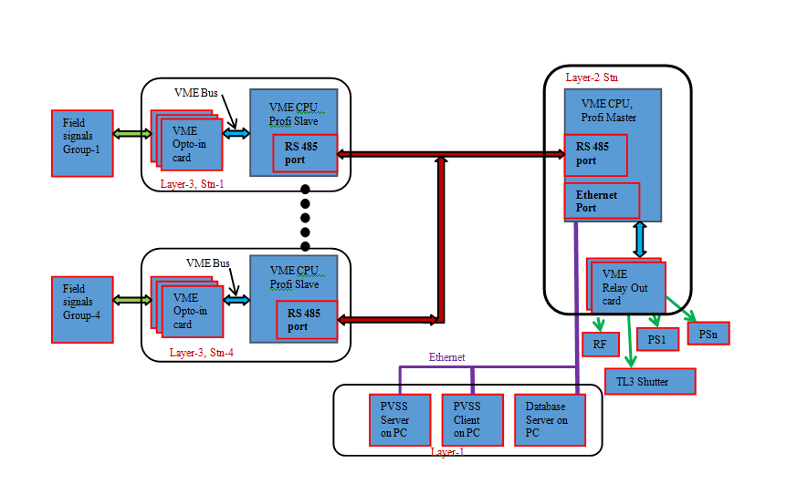 |
| Fig: MSIS Scheme Diagram |
| |
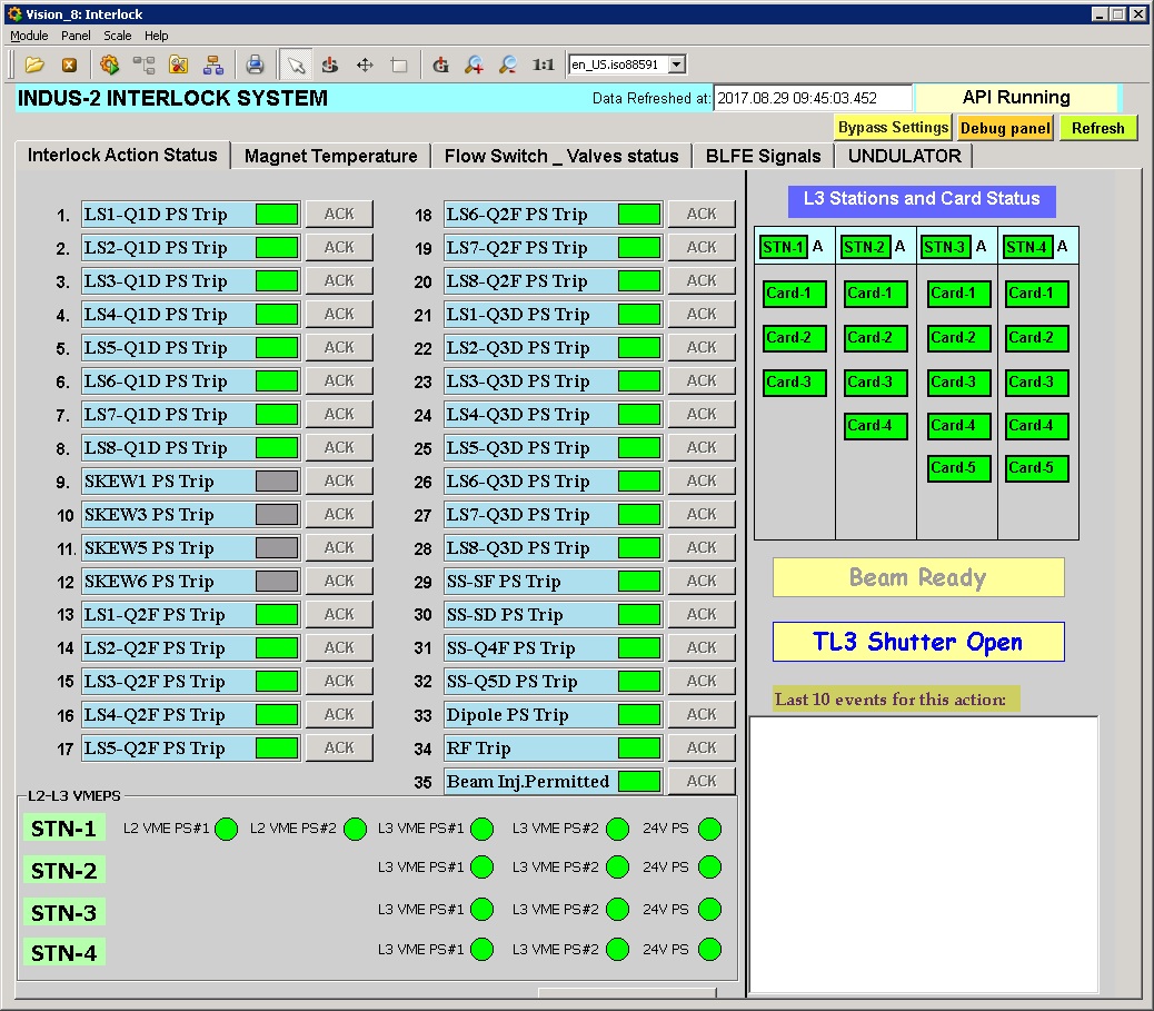 |
| Fig: Screenshot of Machine Safety Interlock System Software. |
Subsequently several important enhancements were incorporated in phased manner with the aim to reduce the spurious trips, capture transient events and increase the reliability through incorporating measures of self diagnostics and redundancy. Different types of hardware boards, modules were devoped, data acquisition scheme was modified to improve process response time and changes in application firmware of Real Time Operating System (RTOS) at layer 2, SCADA GUIs and database were carried out.
Measures for Reliability Enhancement of Machine Interlock System for Indus-2 were implemented in phased manner. All said modifications and changes were completed and deployed in the system in the long shutdown of Dec 2019.
Hardware
Following enhancements were done at the system hardware level:
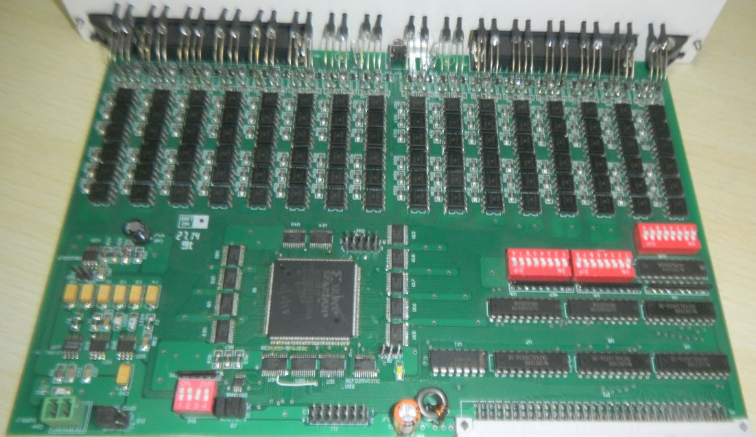
(1) New 32-Channel Isolated Digital Input (DI) Board with self diagnostics feature (Figure1)
The 32 channel isolated digital input boards are replaced with new version which now include self diagnostic feature. All input channels are individually tested at programmed interval. The test data is recorded into the local memory and updated after every test. The actual status of each input channel before the test is kept in different memory location to preserve actual input status. The test results are updated to central database and alarms generated whenever any channel fails.
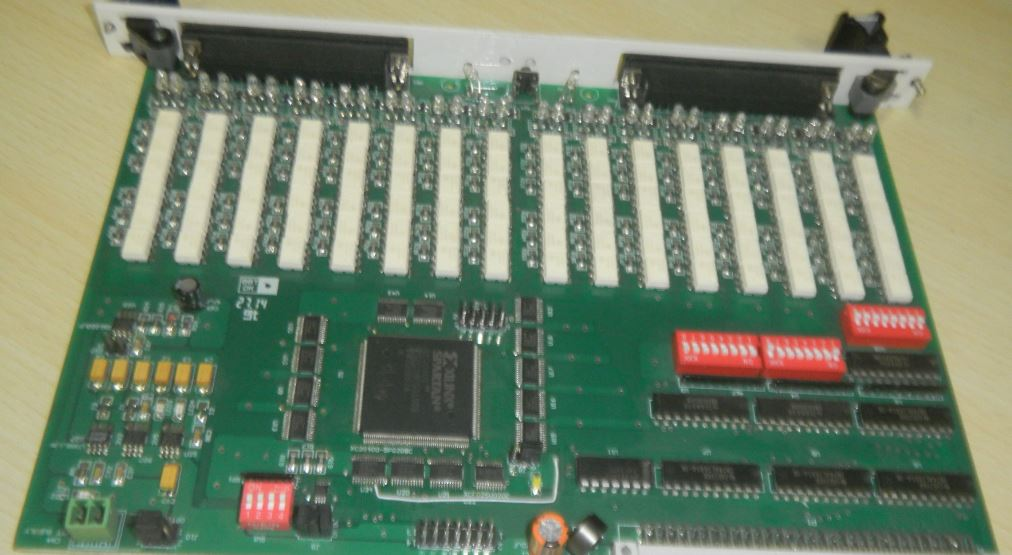
(2) New 32-Channel Isolated Digital Output (DO) board with self diagnostics feature. (Figure2)
The 32 channel isolated digital output boards are replaced with new version which has self diagnostic feature. All channels of this board are repeatedly tested with the help of auxiliary relays at programmed intervals. At the start of the diagnostic test first the actual output conditions are read and accordingly the test is performed. The output contacts remain intact during the test. The test results are updated into central database and accordingly alarms are generated in case of abnormality.
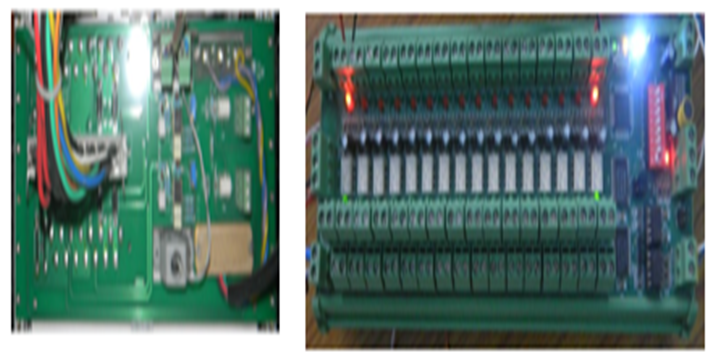
(3) Hot Swappable redundant VME bus power supplies
To enhance reliability and availability of the system for 24x7 mode operation, the VME power supply is used in redundant mode. Current sharing module is developed (Figure3) for VME power supply. It connects with two VME power supplies of same type and lets them work in current sharing mode. Now the faulty VME power supply can be hot swapped.
(4) New 16-channel input signal filtering and latching module.
Filtering and latching of all field signal inputs has been incorporated. This helps to filter out the spurious signals of transient nature and latch and log the inputs which then trigger the trip event. This reduces the spurious trips and helps latch and isolate the actual trip events. Presently thirty eight 16-channel filtering latching and monitoring modules are installed. The modules can be remotely reset to de-latch the inputs when due observations have been made after the trip.
Software
Matchnig software efforts were required at different layers of control system for the above hardware changes and additions. It involved software in SCADA, OS-9, drivers for new boards communication and error handling etc. The software now facilitates various diagnostic tests and error data handling. Database server and webpages have also been modified for adding these new features. Status and alarms are incorporated for card failure, power supply failure and communication failure. Communication speed and system update rate has been improved.
Summary: All above modifications and changes were completed and deployed in the system in the long shutdown of Dec 2019.The system runs satisfactorily in round the clock mode operation. After commissioning of the enhanced system some trip events occurred which were caught and handled as desired without any spurious trip.