Accelerator Controls & Beam Diagnostics Division
Overview - Indus-2 Control System

Any large facility like Indus-2 involves various sub-systems, which are quite extensive in them, all working closely together, towards achieving the desired goals and performance. The control system has the prime task of facilitating the monitoring, supervision and control of all the important parameters of the machine and various sub-systems. To achieve this, it has to interface and interact with various sub-systems at different levels of hardware and software. The control system itself consists of various modules in hardware and software each performing a particular task. Indus-2 control system also consists of various modules or layers in hardware and software and also interconnection links. It follows a certain architecture that highlights the approach followed in designing the system.

 
Design Philosphy - Indus-2 Control System

The control system would be based on master slave architecture enabling functional and physical separation and placement of hardware and software modules across the entire gamut of control system components. Strong and fast network support is the backbone over which various hardware and software components would talk to each other in such a system. The system would generally allow the operation of any sub-system from any console in the main control room. It would be possible to control the entire machine from a minimum number of operator consoles. The system would be such as to minimize the cabling over long runs of cables for minimum interference possibility. The control room should see only essential communication and minimum instrument cables brought inside to reduce the cabling clutter and maintenance efforts. Operations would be achieved with software panels and switches as far as possible. Signals would be concentrated, multiplexed and preprocessed in the field as far as possible to achieve the above objective. Standard signal levels, connectors, control modes etc. would be used across all sub-systems as far as possible.

 
Architecture - Indus-2 Control System

Based on the above design philosophy, Indus-2 control system uses a modular and distributed architecture at various levels. The control system is divided into a number of intelligent subsystems each of which autonomously controls a specific subsystem such as magnet power supplies, RF, vacuum, Beam diagnostics, etc. Identical hardware and software modules are used to perform tasks of same nature.

The control system is distributed over three layers namely User Interface layer (UI), Supervisory Control layer (SC) and Equipment Control (EC) layer.

The upper layer known as User Interface Layer consists of computers for operator console, file servers, data base managers, alarm managers, consoles for software development, etc. These computers are connected over switched Ethernet LAN. These computers possess high computing power and excellent graphics capability to provide good data presentation features. Each of the control room computers can access any of the computer connected to the higher-level network.

Indus-2 architecture
  Figure: Indus-2 Architecture

The computers designated as operator consoles allow the operator to run and supervise several control and monitoring processes simultaneously by means of windowing tools. Two special computers function as file servers, one active and the other standby. There are independent computers working as data base servers to keep the log of the machine parameters and status. In addition, a number of computers are connected on the same network to display the status and other information as and when required. The second layer is the Supervisory control layer that consists of Supervisory Controllers (SC) performing the task of supervisory control and data acquisition. These computers are responsible for the proper operation of a single subsystem. One SC is assigned to one subsystem. SCs receive commands and set values from the operator console over network. SC is connected downward to the EC layer by Fieldbus.

The third layer consists of Equipment Controllers (EC). These microprocessor-based intelligent units form the backbone of the control system. These ECs will be connected to SC, dedicated to a particular subsystem of the machine. All equipments in the field are interfaced to control system by ECs. Each EC controls and monitors the equipment it is interfaced with, according to the tasks assigned by the SC to which it is connected upwards. It continuously monitors the status of the equipment and reads various parameters for their current values and sends this information to concerned SC on request.

This distributed and modular architecture makes the system flexible to accommodate necessary upgradation that may be needed in future. The use of distributed, intelligent modules also helps to improve the overall system response.


Hardware - Indus-2 Control System
According to architecture, hardware is distributed over three different layers:
User Interface Layer - Hardware - Indus-2 Control System

Hardware at this layer consists operator consoles, intelligent terminals, application servers, file servers, database servers and computers for software development. High performances PCs are used at user interface layer. The servers provide services like auto backup, error logging, controlled access (user authentication) etc. These work in the redundant mode with capability of auto switching. Operator consoles provide excellent graphic environment for user interface development.

 
Supervisory Control Layer - Hardware - Indus-2 Control System

The second layer is the Supervisory Control (SC) layer or Layer-2 as shown in the block diagram above. The Supervisory Control (SC) layer or Layer-2 consists of Supervisory Controllers designed around industry proven VME bus architecture. These controllers are responsible for the proper operation of a single subsystem e.g., Magnet Power Supplies. There are other subsystems too like Vacuum, RF and Timing etc, which are controlled by dedicated SCs. These controllers work around MC68040 microprocessor based CPUs with on board Ethernet controller and are VME bus masters. Each VME bus crate at SC layer includes one or more field bus controllers as I/O boards. For some of the subsystems, these crates have dedicated I/O boards e.g. ramping clock generator board etc. The CPU receives commands and set values from the operator console over Ethernet network. It is connected downward to the Equipment Control layer (Layer-3) by Field bus (Profi Bus). Each SC may handle a number of ECs. All the software modules at Layer-2 run on OS9 platform. Main functions of Supervisory Controllers will be-

  • To acquire data from ECs (Layer-3), process the same and communicate the relevant data to control consoles at Layer-1.
  • To receive the control messages from the operator console, parse the same and distribute these to related Equipment Controllers (at Layer-3).
  • To carry out autonomous actions like checking the operations of subsystems that they control, and execute the close loop control wherever applicable.
Equipment Control Layer - Hardware - Indus-2 Control System

ECs are interfaced to various accelerator subsystems like power supplies, vacuum pumps, gauges and controllers, rf system equipments, safety and interlock systems etc. These are designed around VME bus modular architecture and consist of CPU board, Profibus controller board, VME power supply and individual equipment control modules. The details are shown in Figure 7.2. Each EC has MC68000 microprocessor based controller (CPU) sitting on the VME bus along with a Profi-bus controller and the required I/O boards (DAC, ADC and DI/O).

The Profi-bus controller in each of the ECs is connected to the field bus mastered by Profi-bus controller at Layer-2 in multi-drop fashion. Profi bus is a field bus, which in this particular case uses RS 485 as physical media and Profi protocols. The RS 485 link is powered by isolated power. Each EC controls and monitors the equipments it is interfaced with, according to the tasks assigned by the Supervisory Controllers to which it is connected upwards. All the software at this layer run over OS9 platform. ECs continuously monitor the status of the equipments, read various parameters for their current values, and send this information to concerned Supervisory Controller on request. The hardware and software is distributed in three layers each of which is having some intelligence.

There may be nearly 150 ECs all around the Indus-2 machine. Each EC may include some of the following types of VME boards:

  • Controller board (based on 680x0 CPU)
  • Communication Controller Board (Profi Controller)
  • Interface module (ADC, DAC, Digital I/O)
  • ADC board (12 bit, 16 bit)
  • DAC board (16 bit, 18 bit)
  • Digital Input boards (32 channel each)
  • Relay Board
  • Ramp board
  • Timing Delay Generator Board
Software - Indus-2 Control System

Like hardware, software is also distributed over three layers namely User Interface Layer, Supervisory Layer and Equipment Control Layer.

 
User Interface Layer Software - Software - Indus-2 Control Systems

Layer 1 software, which is also termed as Graphical User Interface (GUI), handles user interaction and provides a means of communication between user and accelerator machine. It mainly deals with user requirements and should respond each of the user actions. Such application software on a host can run with non real time operating system. The response to user interaction should be with in the human acceptable limits (500 milliseconds to 1 second). Similarly database updating may be at the rates of 1 second to few minutes and more according to requirements. Application software at layer 1 has to communicate with supervisory (SC) layer for data acquisition and control initiation.

 
Supervisory Control Layer Software - Software - Indus-2 Control System

The software at this layer is for the data acquisition and control. The requirements at this layer are fast, multi tasking performance, good network communication facilities and a convenient environment for software development and debugging. Supervisory level software has to manage two network interfaces, Ethernet for upper layer and Profibus for lower layers.

Software requirements at this level are mainly governed by machine side. The main task at this level is to get data from EC at regular time interval or on demand, and provide a response to any communication received from the layer 1 like transmitting a block of data or initiating the action to change the status or set the values of parameters of the subsystem it is designated to. Real-time operating system OS-9 is used at this level. Availability of powerful development tools such as editor, source level debugger and compilers help to develop the required applications conveniently.

OS-9 supports TCP/IP protocol on Ethernet with native programming environment and optionally cross-development facilities under UNIX, WinNT over network. Code is written in C language and after compilation downloaded on VME crate over network using FASTTRACK tool, supported by Microware.

 
Equipment Control Layer Software - Software - Indus-2 Control System

EC software is almost dedicated to a particular task and confines to a group of instruments. Its basic function is to access equipment parameters and report its status to supervisor when demanded. It also controls the equipment according to user requirements and commands. Additionally, it has to execute diagnostic tasks related to hardware interfaces like ADC, DAC calibration with respect to reference source provided on board and report and correct accordingly. A dedicated software in coordination with upper layer, provides total accessibility of equipment at remote control location. Software at this layer can also respond to any abnormal behaviour of equipment at this level, like abnormal heating, failure of cooling channel, etc. These functions more or less depend on design of the equipment and the control and monitoring action provided. For control action, data has to flow from user to EC and then to machine and for monitoring data has to flow from EC to user layer. The response time of the system is important for user point of view. The total response time for any command is from user to equipment and then back to user, for feed back. This is expected to be in the range of few hundred milliseconds to 1 second.

The software for layer is written in C code and downloaded to EC after compilation. It consists of various modules like I/O modules (drivers and descriptors), Command/Response (C/R) modules, alarm modules, special modules like magnet cycling module & ramp generation module etc.
I/O modules contain descriptor for each I/O point specifying characteristics like conversion parameters and offsets.
C/R modules handle the data exchange between EC and SC. It parses the message received from SC and convert the same in the proper format for EIU to take appropriate action.
Alarm modules test the status of equipments and report abnormal conditions for taking proper action. Then may then inform the SC of the action taken.
Ramp generation modules calculate the required parameters for the ramp and the ramping process is initiated and controlled with synchronizing pulses.


Subsystems - Indus-2 Control System
Following subsystems are being used in operation of Indus-2.
Magnet Power Supplies Control System - Subsystems - Indus-2 Control System

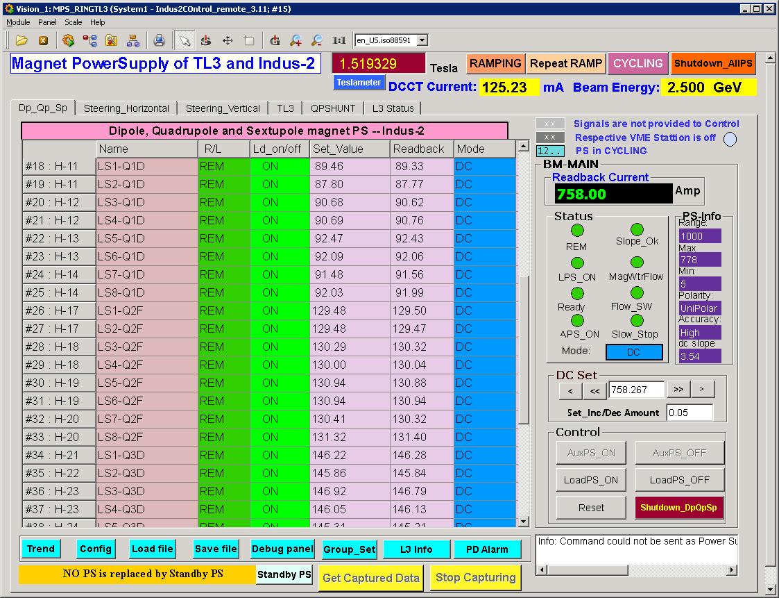
The Control System for Magnet Power supplies (P/Ss) of Indus-2 is one of the systems that is used to set up the dynamics of the beam in the accelerator. The control system facilitates setting up the different magnet P/Ss for beam injection, ramping and storage at the higher energy levels. The beam dynamics pose different requirements for all these phases. The flexibility to operate P/Ss in different modes and catering the stringent accuracy and stability requirements are the features of the system. The best of the accuracies of the references is 50 ppm maintained at the supplies inputs. This is assured by the hardware. The system provides a very flexible, fully programmable and synchronous energy ramping and the magnet cycling procedure. The system also provides the diagnostics information to the operator level. The ramping system also facilitates the ramping of RF voltage synchronously, a typical requirement from an accelerator. The present control system is the third version after various reviews. It is being operated daily without hurdles though the system is not absolutely trouble free.

DAE_RRCAT_INDORE
Fig: Screenshot of Magnet Power Supplies Control System Software.

Vacuum Control System - Subsystems - Indus-2 Control System

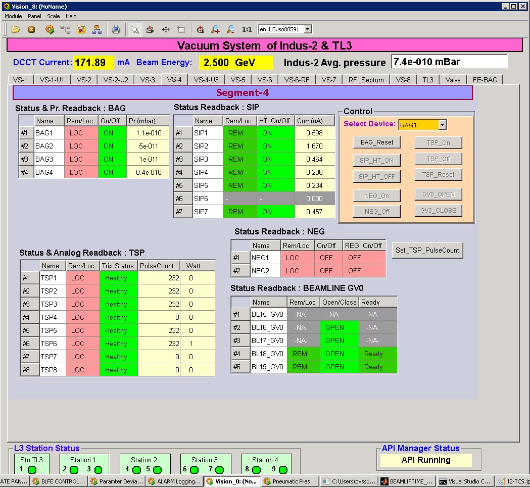
Vacuum system in Indus-2 is widely scattered and uses differing kind of devices viz., pumps, gauges, isolation valves, Residual Gas Analyzers (RGA), temperature monitors etc. The Control System for Vacuum (VCS) monitors and controls all such devices. The specialty of this control system lies in its interface to the diversified type of devices. Provision to incorporate more devices in future is made. The partial pressure of the gas components in the vacuum chamber of Indus-2 is available from 16 RGAs. New software with substantial capabilities was developed to integrate the RGA system to VCS. The Thermocouple Interface Unit (TCIU) monitors temperature of vacuum chambers of Indus-2. Software was developed for this system in LabView. The software reads 20 no�s of TCIU units on multi-drop RS 485 link. The temperature information is also provided to Machine Safety Interlock System (MSIS) as temperature interlocks. The System has alarm generation, data logging to central database and various diagnostics features. Later both RGAs and TCIUs are also integrated with VCS.

DAE_RRCAT_INDORE
Fig: Screenshot of Vacuum Control System Software.

R. F. Control System - Subsystems - Indus-2 Control System

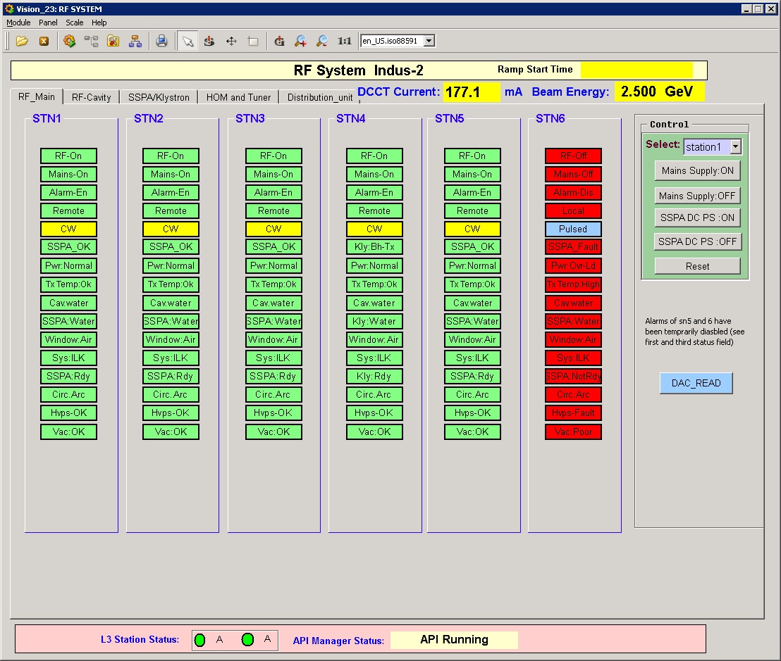
The RF control is fully implemented for all four cavities. A parallel operator console is also provided in the far off RF system hall. This was required temporarily for but its usefulness made it a permanent feature and it is now regularly used. All RF systems are under a full fledged local RF supervisory control system which is a superset of the remote control system for RF. The RF control system is interfaced to this local RF control station. This allows the filtering of some of the control actions which are critical to the RF systems. Monitoring of the parameters is available on both the systems. Virtually the two control systems work on a single system.

DAE_RRCAT_INDORE
Fig: Screenshot of R. F. Control System Software.

Beam Diagnostics Control System - Subsystems - Indus-2 Control System

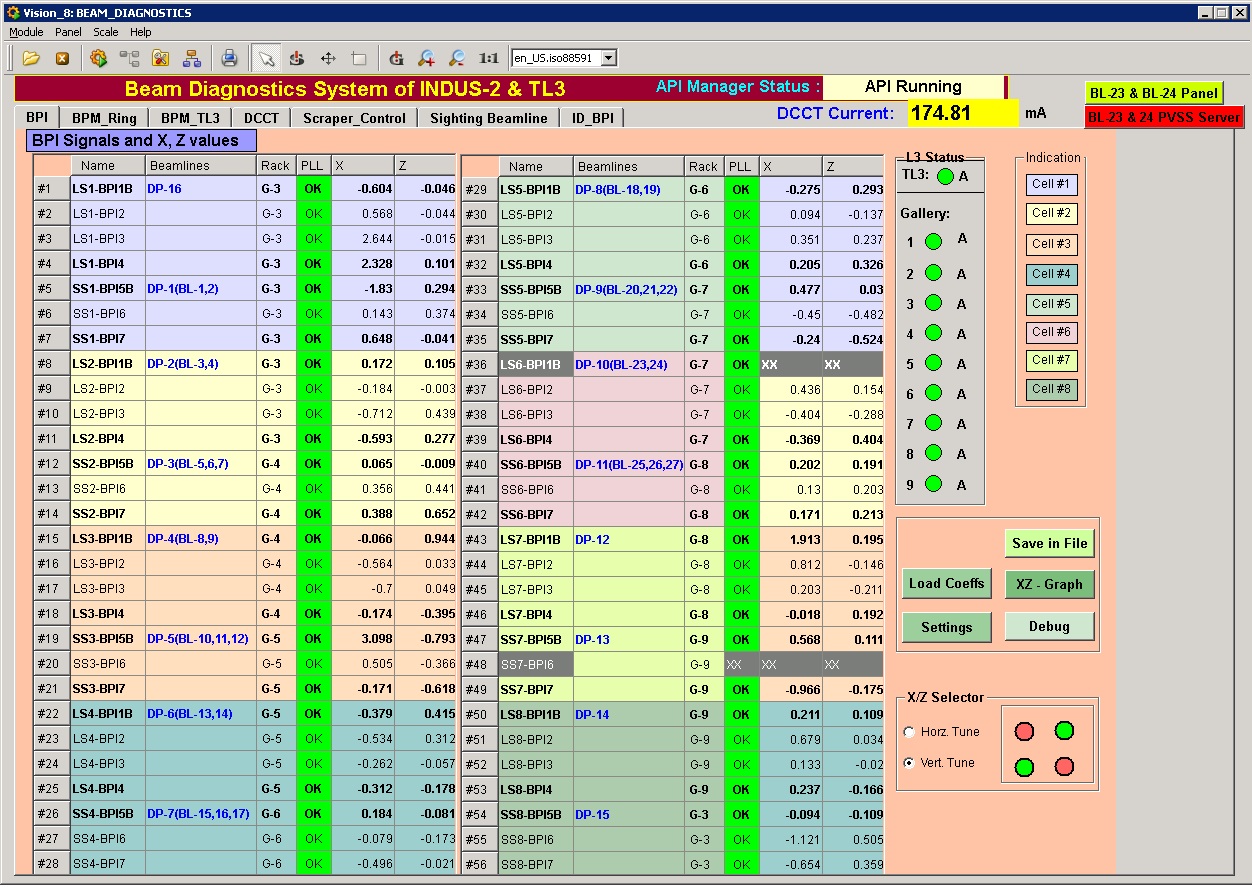
This system controls all beam diagnostic devices placed in TL3 and Indus-2 ring. Recently control of sighting beam line was added to this sub system.

DAE_RRCAT_INDORE
Fig: Screenshot of Beam Diagnostics Control System Software.

Radiation Safety & Surveillance System - Subsystems - Indus-2 Control System

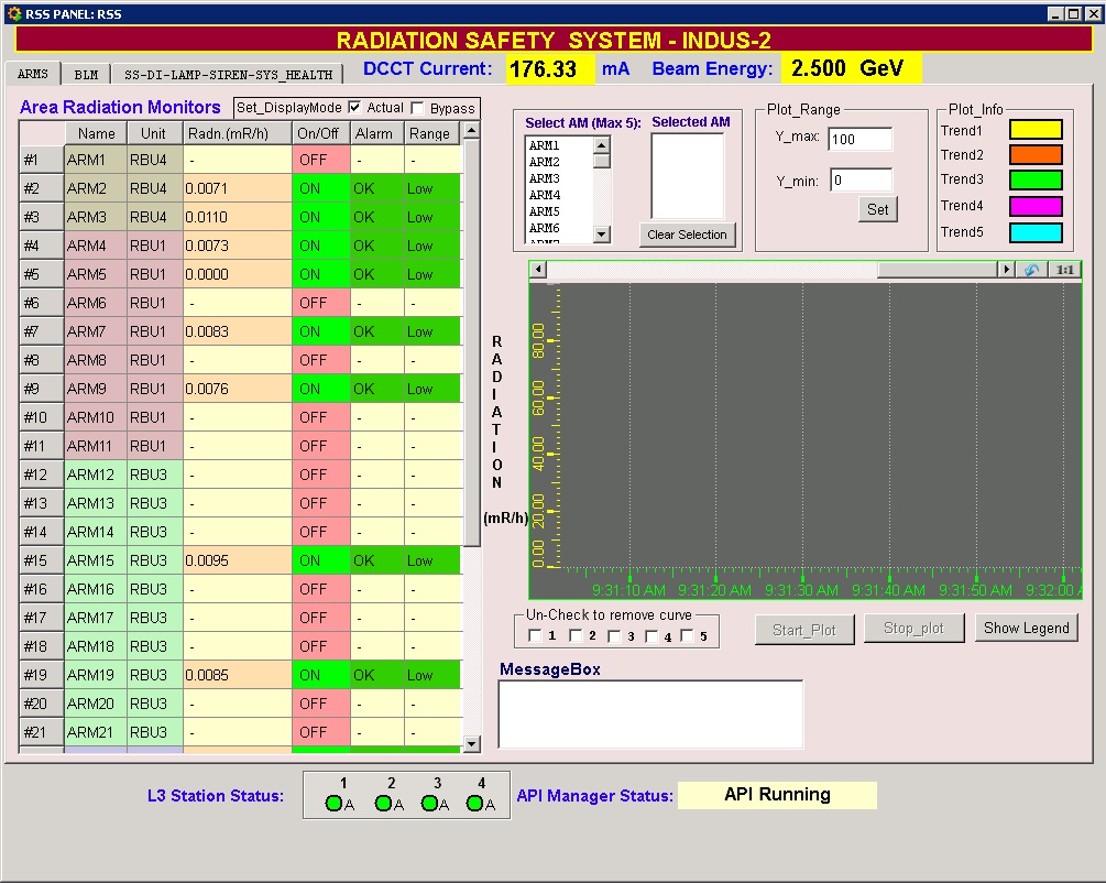
The control system for Radiation Safety & Surveillance System (RSS) monitors the radiation levels all around Indus-2 accelerator complex. It handles about 52 radiation monitors and various safety devices. The control system issues warnings and alarms when radiation levels reach some prefixed critical values. It also display and plot the radiation dose rate of all the radiation monitors. Status of protection and warning devices viz., Search and Scram switches, Door Interlocks and Flashing Lamps is displayed in the control room. It also facilitates data logging of all the parameters for future reference and analyses. There are about 225 Digital Input and about 52 Analog Input signals interfaced to RSS Control system.

DAE_RRCAT_INDORE
Fig: Screenshot of Radiation Safety & Surveillance System Software.

LCW Control System - Subsystems - Indus-2 Control System

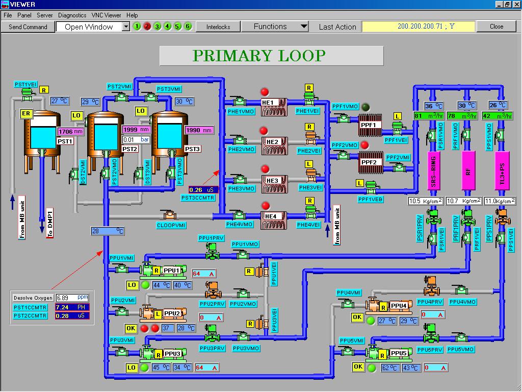
The first system to be commissioned was the control system for Indus-2 LCW plant. LabView ver 6.0 was relied upon to build the system software. The system monitors about 700 parameters and provides features like re-configurability in control actions and requirement of dealing with slower devices viz. electrical valves which take about 20 seconds to operate. In addition, the sequential operation of such devices slowed down the over all performance of the system. The Concept of event driven architecture was brought in to rescue from the problem. The advantage of this architecture was further realized when the number of parameters increased to 1500. The control system fulfilled the requirement of a standalone plant control system and later integrated in the main control system of Indus-2.

DAE_RRCAT_INDORE
Fig: Screenshot of the LCW Control System Software.

Timing Control System - Subsystems - Indus-2 Control System

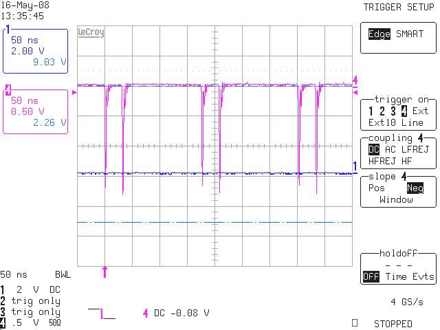
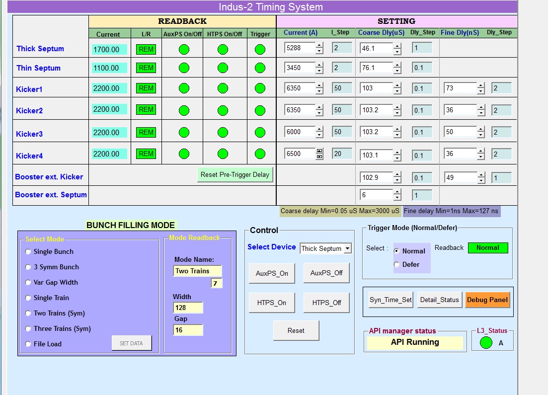
Time synchronization of the pulsed devices is very critical in accelerators. The criticalness is more on the trigger event generators for these pulsed magnets. The RF frequency of operation in Indus-2 is higher and different than that of Booster (BR). Extraction of two bunches from BR and their injection into specific bucket(s) out of 291 buckets in Indus-2 requires very tight synchronization of timings of the pulsed devices. On the top of that there exists requirement of different filling modes in the Indus-2 namely Single bunch filling, Three Symmetric bunch filling and Multiple bunch filling mode. All these complexities are dealt by the Timing Control System. RF frequency of Indus-2 is 505.8 MHz, which poses very tight requirements on the Timing and Trigger part of the control system including maximum jitters of the order of 1 nsec between the trigger signals of ext. kicker and four Inj. Kicker power supplies. To generate accurate time delays with jitters within the specified tolerance multi channel coarse and fine delay generator cards were designed.

DAE_RRCAT_INDORE
Fig: Three symmetric bunches filling screeshot

To support required filling modes coincidence generator card was designed using ECLin PS family operating at 505.8 MHz. To further optimize the performance and reduce the conductive path lengths of different inter-card signals, all these cards were redesigned using FPGAs internally operating at 100MHz.

In addition the control system also monitors and controls the power supplies for these pulsed magnets.

Noise resulting from high dI/dt of the pulsed devices required lot of efforts to bring the control system to operating level although all the outputs and inputs are isolated type. Adequate noise filtering and noise suppression techniques were applied to combat with such noisy environment.

DAE_RRCAT_INDORE
Fig: Screenshot of Timing Control System Software.

Alarm Handling System - Subsystems - Indus-2 Control System

Of the late introduced the Alarm Handling System (AHS) alerts the operator of any abnormality in the machine parameters, e.g., supply trips, faulty status, interlocks etc. The audio alerts immediately draw the attention of the operator. The alarming parameter can be seen and acknowledged on the system display. The happenings are categorized as alarms and events. The alarms and events are logged with detailed information about their origin. The Alarm history can be displayed on web. Measures have been taken to avoid occurrence of spurious alarms. The AHS uses central database for alarm generation thus it is possible to include any number of parameter in the alarm list.

Screenshot of Alam Handling System Software.


Machine Safety Interlock System - Subsystems - Indus-2 Control System

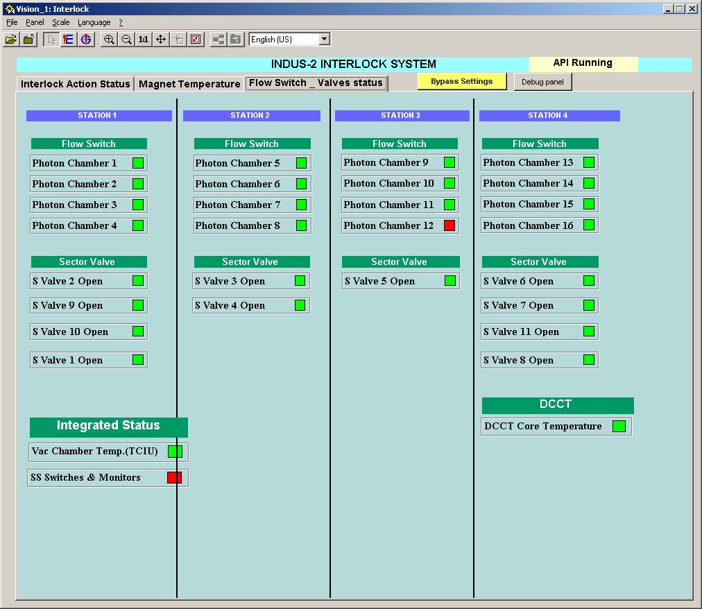
The centralized Machine Safety Interlock System (MSIS) is implemented for protection of critical machine components like magnets, photon chambers, DCCT, sector valves etc. Over temperature and flow switches mounted on the components provide temperature status. The MSIS gives a trip signal to various devices when any of the High Radiation status, over temperature or TCIU status is found bad. Later BLFE interlock and emergency beam dump request from beam line users etc, will be incorporated in the MSIS. The typical use of control interlock contacts and the architecture guarantees failsafe operation of accelerator w.r.t. power/power supply failure, processor and communication failure. Interlock system always polls all the input status and sends all information to supervisory control crate. RS485 is used for communication between L2 and L3. Control actions are taken at layer L2.

DAE_RRCAT_INDORE
Fig: Screenshot of Machine Safety Interlock System Software.

Beam Line Front End (BLFE) Control System - Subsystems - Indus-2 Control System

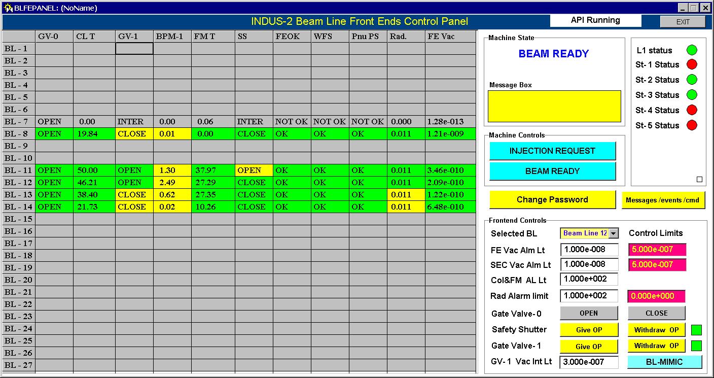
Indus-2 Beam Line Front Ends (BLFE) control system was developed to protect the machine vacuum from beam line failures and vice versa. This allows a well co-ordinated and safe usage of machine by its users. This system involved design complexity, as it had to control vacuum gate valves, safety shutters in presence of a local control system at front end. The software automatically closes the gate valves when the vacuum degrades on the either side of the front end. Beam injection request and giving permissions for valves and safety shutters is password protected so that only authorized operator may operate. The control system also provides facility of logging beam usage and experiment related information for administrating Indus-2 utilization.

DAE_RRCAT_INDORE
Fig: Screenshot of BLFE System Software.

Global Slow Orbit Feedback System - Subsystems - Indus-2 Control System

A global slow orbit feedback system has been designed using Matlab and PVSS.

Best viewed in 1024x768 resolution