| Controls, Diagnostics and Beamline Instrumentation Division |
| Vacuum Control System |
|
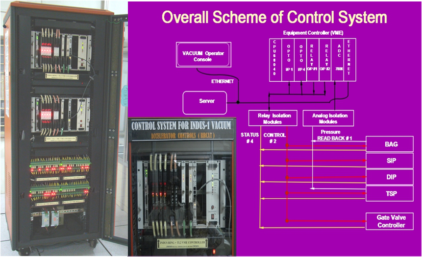
The Indus-1 VCS has a two layered architecture(L1-L2). It monitors and controls the Vacuum devices SIP, DIP, TSP, Penning Gauge & ION Gauge of Indus-1 storage ring, Booster, Microtron, TL1 and TL2. The VME Equipment Control Unit (ECU) is installed using Motorola 68040 CPU, digital I/O and analog I/O peripheral boards. ECU communicates with server over Ethernet. Each digital signal is isolated with relay isolation module and each analog signal is isolated using analog signal conditioner. Total number of signals are ~500 numbers of 60 vacuum devices. The overall scheme is shown below.
|
| |
 |
 |
| Figure-1: Hardware Scheme[Full Size Image] |
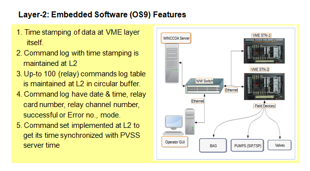
Figure-2: Layer-2 Embedded Software (OS9) Features[Full Size Image] |
|
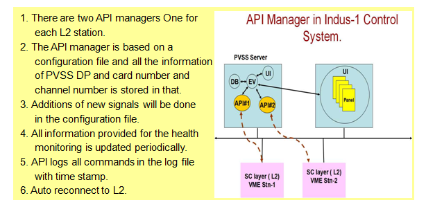
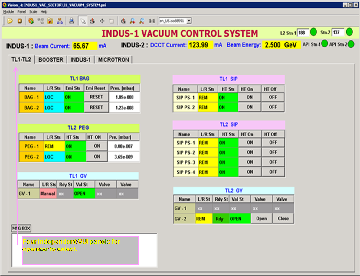
VCS - API is an extension manager of WINCCOA SCADA software, developed in C++. VCS-API interfaces with the VCS-ECU at one end and to WINCCOA system at the other. It periodically polls the VCS-ECU to get field data and updates the WINCCOA database. It also takes the various user commands and passes them to VCS-ECU. VCS-GUI of WINCCOA system provides HMI to the operator to monitor and control various devices of Indus-1-VCS. The updated field data through WINCCOA DB is displayed in tabular and graphical form. The VCS alarm panel alerts the operator if any of the vacuum system pump goes off. Also if ring pressure crosses the set limit an audio alarm raises to draw attention of operator. Data-Logging of all read-backs, set-values and status signals is done @1Hz. The history data is made available on web.
|
| |
 |
 |
| Figure-3:Layer-1 API Manager Features[ Full Size Image] |
Figure-4:GUI Software[Full Size Image] |
|


