Controls, Diagnostics and Beamline Instrumentation Division
Supervisory Control System for Horizontal Test Stand (HTS)
The bare Superconducting RF (SCRF) cavities are first tested in Vertical Test Stand (VTS) with low power RF. After the bare cavities pass VTS test, they are dressed by jacketing them inside a Helium Vessel and attaching tuners, RF power coupler and other devices. Horizontal Tet Stand (HTS) is used to test and qualify the dressed cavities at higher RF power.
There are numerous sensors, instruments and devices in the system which are needed to operate the machine and monitor various signals. A supervisory control system has been developed and installed to integrate these sensors and instruments and provide their data and control at a centralized control room for operator to monitor and control the HTS. Presently the system caters to about 250 signals.
There are five main sections to this control system:
VME based Data Acquisition and Control System
Search and Scram System
PLC based Machine Protection System (MPS)
VME based Cryostat Demagnetization System
LabVIEW based Graphical User Interface (GUI)
Various sensors and instruments that have been interfaced with control system are as follows:
Temperature readout units (Cernox & PT100)
Liquid He (LHe) level meters
Mass flow meters
Air flow meter
Area Radiation Monitors (ARM)
Radiation rate meter
Oxygen monitor
Electro-pneumatic valve actuators
Pressure sensors
Vacuum gauges
Fluxgates (magnetic field sensors)
Power supplies for heaters
Power supplies for magnetic coils
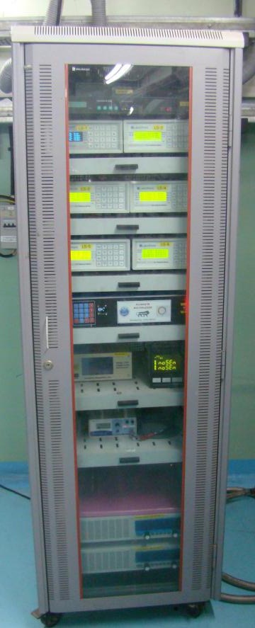
Figure-1 shows the instrumentation rack housing various devices, meters and readout units for the sensors.
Fig.1: Instrumentation rack
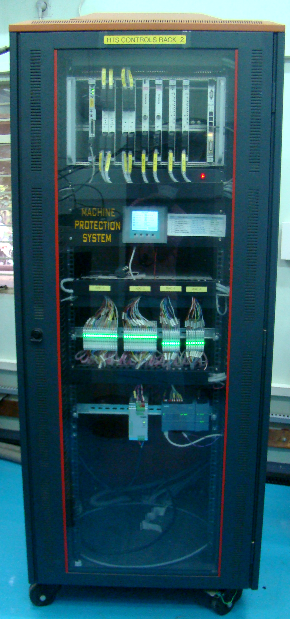
Fig.2: VME based Data Acquisition and Control system
(1) VME based Data Acquisition and Control System:
There is a VME based system for Data Acquisition and Control of various machine parameters. It consists of a CPU board running RTOS applications and a number of analog and digital input and output boards as shown in Figure-2. Various signals interfaced are of type 4-20 mA, 0-10 V and digital signals like potential-free contacts, open collector etc. Presently, system can cater to 180 signals. Isolation has been provided for all the signals.
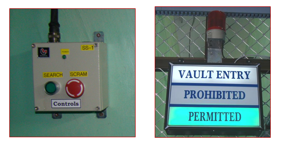
(2) Search and Scram System:
A search and scram system (Figure-3) has been developed and installed for personnel safety. This is used to ensure that no person is present in the vault before powering the cavity. The system includes hooter, flashing lamps and display board.
Fig.3: Search and Scram System
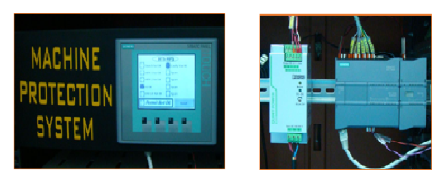
Fig.4: Machine Protection System
(3) PLC based Machine Protection System:
A PLC based Machine Protection System has been developed (Figure-4) which takes a number of critical signals from the system (like oxygen level, radiation level, He vessel pressure, LHe level etc.) and generates safety permit signal that goes to other sub-systems. The machine operation is allowed only if the parameters are in safe state.
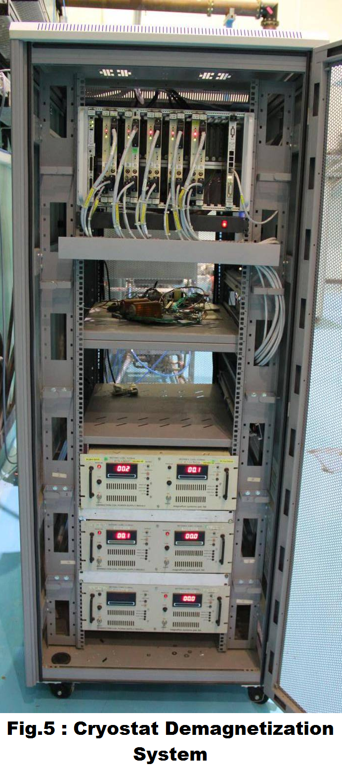
(4) VME based demagnetization system :
A VME based system has been developed to perform the demagnetization of HTS cryostat. It consists of a VME crate with CPU board running RTOS applications and five sets of ADC and DAC board with 16-bit resolution. Using this system the magnetic field at various points on helium vessel is reduced to desired values.
Figure-5 shows the Control system rack with VME crate at the top which has been interfaced with the power-supplies placed in the lower section.
(5) LabVIEW based GUI:
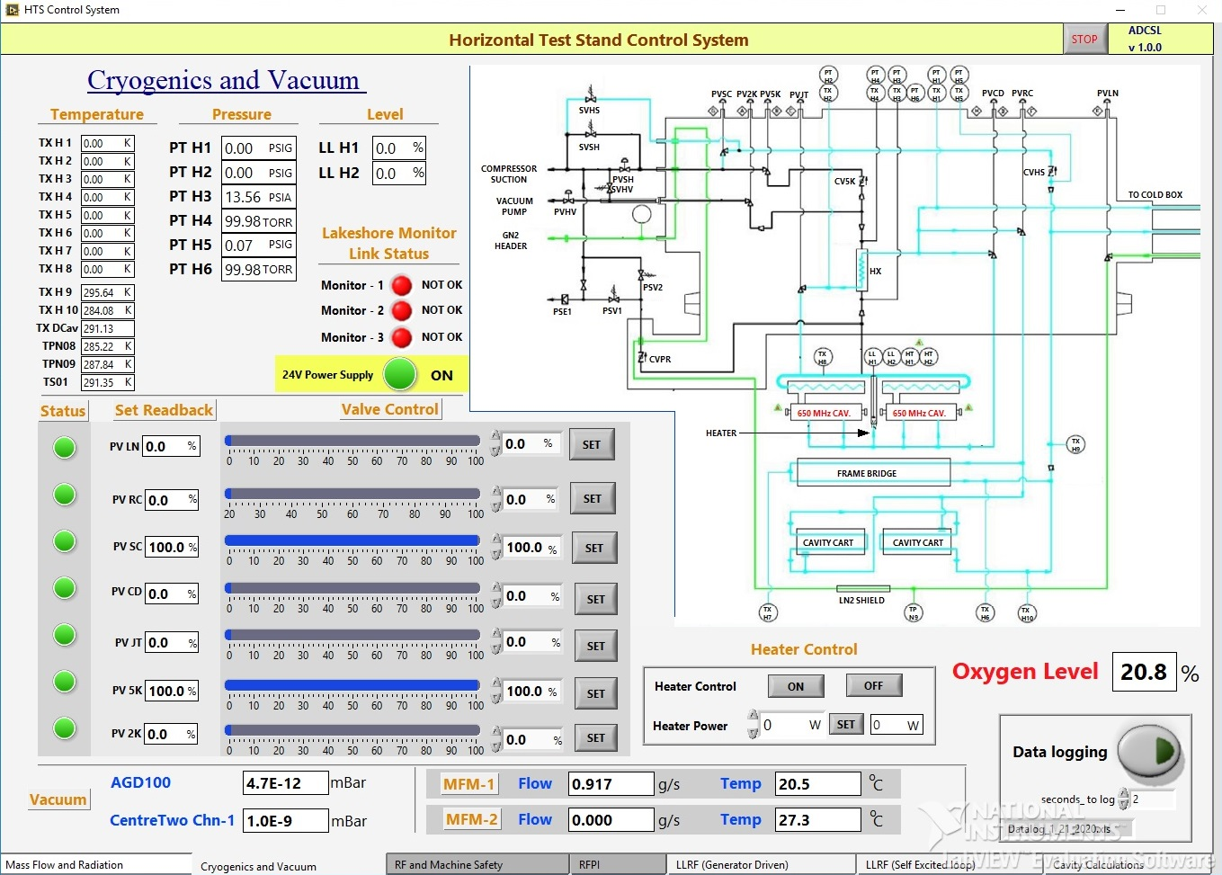
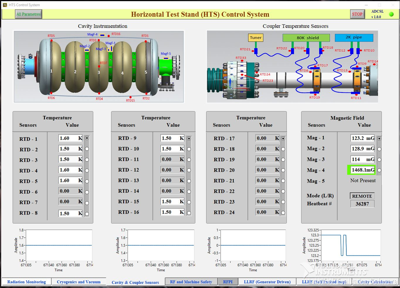
Labview based GUI screens have been developed which presents a comprehensive view of all the readback parameters and setting of all the controlled parameters of the system. There is a screen to operate various valves and monitor various sensors for cryostat cooldown operation (Fig-6.a). There is a screen to show the readings of various sensors mounted on cavity and coupler (Fig-6.b). There are also GUI screens for remote operation, value setting and readback of power-supplies used for cryostat demagnetization and performing current cycling operation .
GUI also provides facility of logging the data at user selectable rate. The software communicates with VME stations over TCP/IP and with certain instruments over RS-232 and RS-485 (Modbus).
Fig.6a: GUI for cryostat cooldown operation
Fig.6b: GUI for Cavity & Coupler Signals
For the deployment of the system, operation and interfacing of various instruments was tested. Hundreds of meters of cables were prepared and laid in the field to connect the devices to control system. Using this control system,cooldown trials of HTS cryostat and several rounds of SCRF cavity testing have been performed successfully, while monitoring and controlling the signals from the control room.