Cryocooler Development at RRCAT
Several scientific and technological applications require low temperatures in the range of 10 K - 70 K, with rather modest heat load requirements of a few watts. One important example is cooling of devices like infra-red optical detectors, parametric amplifiers and cryopumps. Cryocoolers are particularly convenient and economical systems for this purpose as they dispense with the need of Liquid Helium and the problems associated in the handling of liquid Helium. Cryocooler need only electricity to produce such low temperatures.
Two types of Cryocoolers, 30K and 10K, were developed at Cryoengineering and Cryomodule Development Division (CCDD).
A schematic of such a system is shown in (fig.1). It basically consists of two major subsystems; an Expander Module and a Compressor Module.
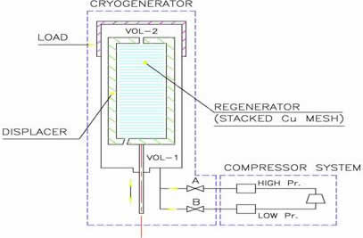
Fig 1: Schematic Diagram of G-M Cryocooler
The compressor Module provides continuous supply of oil-free helium gas to the Expander module through two valves `A' (High Pressure - HP) and `B' (Low Pressure - LP). The Expander module consists of a cylinder and a hollow displacer, which is filled with stacked Cu mesh. The displacer moves up and down inside the cylinder with the help of a motor. The load (cryotip) is placed at the top portion of the cylinder (fig.3).
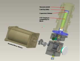
Fig 3: 3D model of Cryocooler developed at RRCAT
When displacer is at the top and valve A is open (valve B closed), high-pressure helium gas enters through valve A and fills the Expander. At this time the displacer is made to descend by the motor, with the valve A still kept open (fig.2).
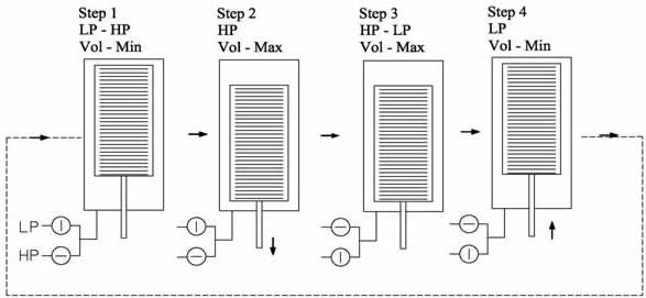
Fig 2: Sequence of Operation for Gifford McMahon Cycle
The gas in volume 1 enters the volume 2 through the regenerator. Once the displacer reaches the lower end, the valve A closes and the valve B opens, thus connecting the Expander module to the lower suction pressure of the compressor system. The gas within the Expander, does work to push out the gas that leaves during this process; therefore, energy is removed as work from the gas finally left in the expansion space. This causes the temperature of the lower pressure gas remaining in the expansion space (Volume 2) to drop to a lower temperature. Now the displacer starts moving upwards, forcing the gas in volume 2 to pass through regenerator. During this passage gas cools the regenerator. In the next cycle when valve A opens, and the displacer is made to descend. The high-pressure gas, passes through regenerator to fill in volume 2 and gets cooled by the regenerator, which was cooled by the outgoing cooled gas in the previous cycle. Once the displacer reaches the lower end, valve A closes and valve B opens, cooling the gas further by expansion. Now the displacer starts moving upwards, forcing the cooled gas in volume 2 to pass through regenerator thereby cooling it, and the cycle repeats. In a single expansion stroke the temperature of gas drops only by about 6 – 8 degrees. This cools the regenerator and after repeated cycles a steady state is reached. In steady state, if for example the machine is operating at 50 K, the gas cools from 300K to 50K in the regenerator itself and the temperature would further drop by 6 - 8 degrees due to expansion. Warming up of this cooled gas to the steady state temperature of 50K represents the actual refrigeration load. The regenerator should be designed to have very high efficiency (typically 99.7%).
A small loss in regenerator efficiency results in a very high loss in refrigeration. Typically a single stage Cryocooler can be used to obtain 30K with reasonable cooling capacity. A cascaded two stage system is required to obtain lower temperatures, say down to 10K with reasonable cooling capacity. Vacuum insulation is provided around the cryotip.
Cryocoolers developed at RRCAT are shown in the photographs (fig. 4).
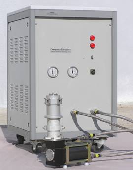
Photograph showing 30 K Cryocooler Developed at RRCAT
Table 1: Cooling capacities of 30K Cryocoolers developed at RRCAT |
Normal Mode |
Optimized Mode |
Model 01 |
|
3W at 50K |
3W at 30K |
|
8W at 50 K |
Model 02 |
|
5W at 30K |
10W at 35K |
17W at 50 K |
20W at 50 K |
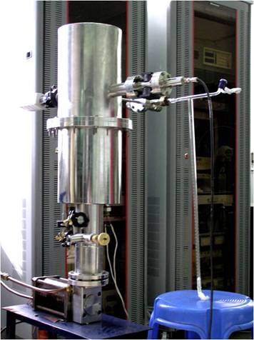
A 10K Cryocooler model has also been developed. It produces a lowest temperature of 8K. Its cooling capacity at 10K temperatures is 1.5W (fig. 5)
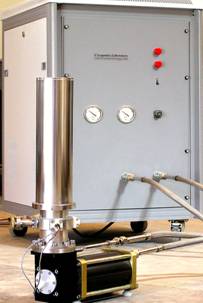
Fig 5: 10 K Cryocooler Developed at RRCAT
The 30K Cryocooler expander consists of a single stage expansion space (fig. 3). In this, copper mesh is used as regenerator material. The 10K Cryocooler expander has two cascaded expansion spaces. In the first expansion space, about 50K is achieved while in the second expansion space temperatures lower then 10K is achieved. In this also copper mesh is used as first stage regenerator material. As copper loses its specific heat very fast below 50 K, lead balls are used as the second stage regenerator material. Lead has higher volumetric specific heat as compared to copper below 50K.
A Compressor module is required to supply pure and oil free high pressure helium gas to the expander modules for their operation. Suitable compressor modules are also developed indigenously, as helium compressor for use in such system are not available in the open market, due to their propriety nature.
Hermetically sealed air conditioner compressors available in the market for Freon gas are used in our compressor modules after suitably modifying them for helium gas compression. Helium gas has very high heat of compression as compared to Freon (Cp/Cv = 1.17 for Freon 22 and 1.67 for Helium). This results in very high exhaust gas temperature. If left unchecked this high temperature not only degrades the lubricating oil, but due to the increased vapor pressure of lubricating oil, it migrates to the expander, leading to temperature fluctuations. To overcome this problem instead of compressing helium gas alone, oil gas mixture is compressed. Oil having higher mass specific heat in the mixture, caries bulk of the heat produced during compression. Now this oil has to be cooled to ambient temperature and returned to the compressor for continues maintenance free operation. Before the high pressure helium gas is passed to the expander module, traces of oil have to be removed from it, typically to a level of less than 5 ppm. This has been achieved quite successfully by us. Selection of the lubricating oil as well its processing is a complicated task. Proper selection as well establishing the process parameter along with processing procedures is another time consuming task. Now cryocoolers developed by us are suitable for maintenance free operation over several thousands of operating hours. All our systems, 30 K as well 10K cryocoolers, developed by us have a very good temperature stability (temperature remains stable within ± 0.5) when operated continuously round the clock for weeks. Six numbers of 30K cryocoolers supplied to users labs are working satisfactory since last several years. A refrigerator operated cryopump using 10K cryocooler is also developed. Its specifications practically achieved are given in table 2 and the system is shown in figure 6.
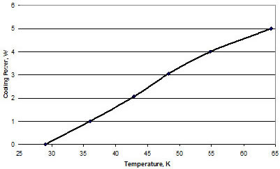
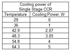
Cooling Power of a Cryocooler:
Advantage of working with a liquid nitrogen or liquid helium cryostat is that it operates under saturated condition. This means the temperature of the liquid remains constant due to the latent heat of the fluid. So if heat load is changed due to various conditions, the temperature of the liquid remains constant (Boiling point at that atmospheric pressure).
In other words on increasing heat load only the boil-off will increase.
The Cryocooler works as a heat pump. It lifts heat from the lower temperature and dumps at room temperature. It has a constant heat lift capacity at any particular temperature. This is high at higher temperature and low at lower temperature. Therefore, the cryocoolers are characterized by its heat lifting capacity at different temperatures. Cooling power of a typical cryocooler is as given below.
|