|
8. Recent development of magnets for Indus Accelerators:
(i) Fast Corrector Magnets (FCM) for fast orbit feedback system of Indus-2:
Synchrotron users in Indus-2 require stable photon beams for scientific experiments in which typical requirement of beam position stability is ≤ 10 % of the r.m.s size of electron beam. This stability requirement demands correction of beam orbit disturbances in the range from DC to 100 Hz using fast corrector magnets. Hence, total 40 numbers of combined function correctors of high bandwidth have been developed for correction of short term perturbations (from low to high frequency up to 100 Hz). These fast corrector magnets have relatively weak kick strengths of ≥ ± 50 μrad at ±15 A DC. The details of magnets for fast orbit feedback system of Indus-2 are given below.
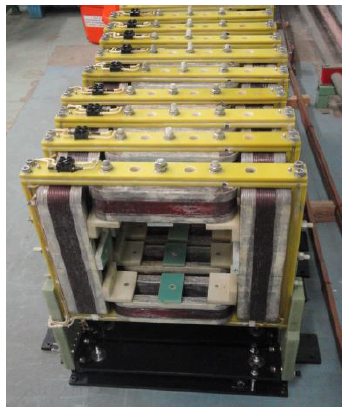
Fig. 91: Fast Correctors magnets for beam orbit corrections for Indus-2.
|
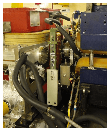
Fig. 92: Installed fast corrector over SS bellow in the limited space at Indus-2 ring.
|
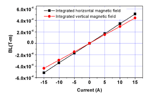
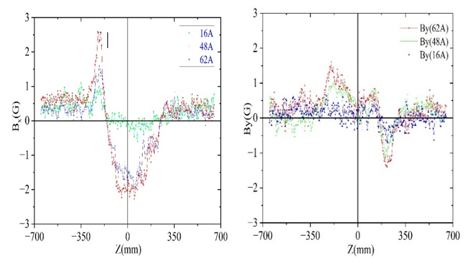
Fig. 93: Integral field strengths (DC) of fast corrector with excitation current.
|
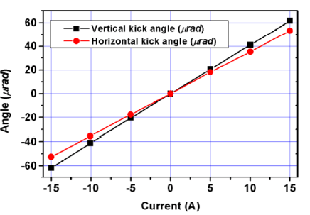
Fig. 94: Angular kick strengths (DC) of fast corrector with excitation current
|
The initial fast orbit local correction results in Indus-2 have been encouraging and corrected the beam orbit variation up to 3 μm in the vertical plane.
(ii) Combined function harmonic sextupole magnets for Indus-2:
Harmonic Sextupole (HS) magnets are required to improve the dynamic aperture by suppressing the non-linearity induced by the existing chromatic sextupole magnets. Due to limitation of space in Indus-2, 32 Nos. of compact combined function harmonic sextupole magnets were designed and developed. These magnets are integrated with additional windings to generate horizontal & vertical dipole and skew quadrupole components. These magnets have integrated field strengths of 17 T/m for harmonic sextupole and 0.1 T for skew quadrupole components & 1.6 mrad kick for horizontal and vertical steering for closed orbit beam corrections.
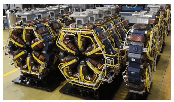
Fig. 95: Harmonic sextupole magnets, showing coils of sextupole, skew quadrupole, horizontal and vertical fields.
|
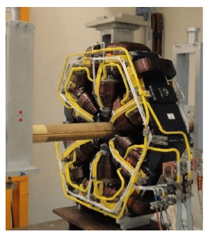
Fig. 96: Magnet characterization on rotating coil harmonic bench.
|
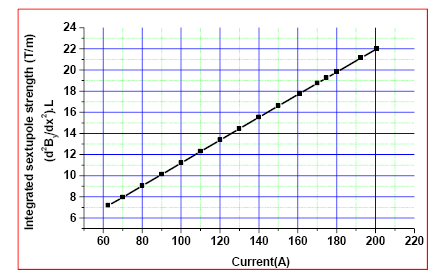
Fig. 97: Integrated sextupole strength of magnet w.r.t its excitation current.
|
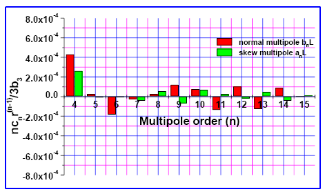
Fig. 98: Integrated multipoles at r = 32mm for only sextupole excitation at 170.15A.
|
Measured integrated strength of each field component in the magnet.
| Field component
| Current (A)
| Integrated strength at r=32mm
|
| Sextupole
| 170.15
| 17.58 T/m
|
| Skew QP
| -10.0
| 0.1036 T
|
| Horizontal Steering
| -9.872
| -1.44E-02T-m (1.72 m rad at 2.5 GeV)
|
| Vertical Steering
| -10.0
| 1.39E-02 T-m, (1.668 m rad at 2.5 GeV)
|
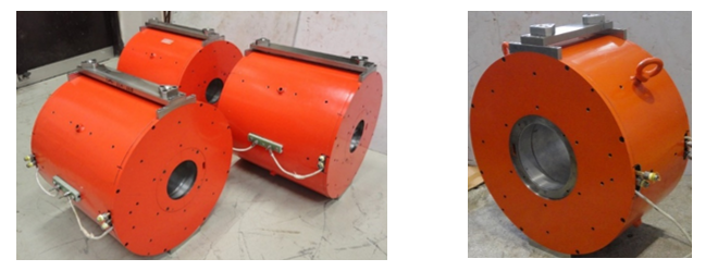
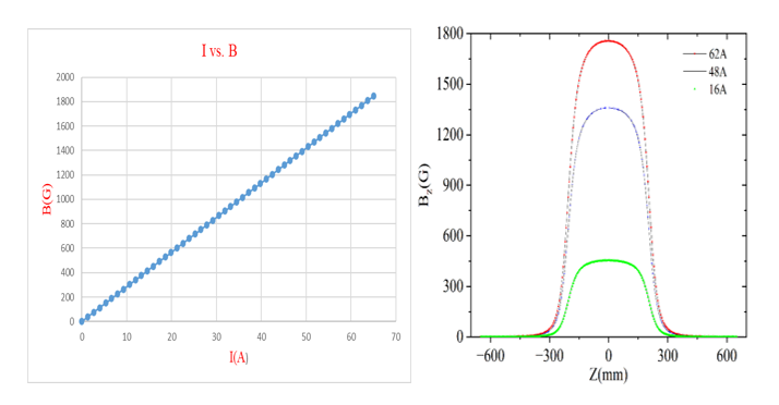
(iii) Vertical Pinger Magnet for Indus-2:
Pinger magnet is a beam diagnostic tool for probing the linear and nonlinear dynamics of the beam by the way of generating betatron oscillations. A vertical pinger magnet is designed, developed, characterized and installed (fig. 99) in SS-7 of Indus-2. This magnet has window type geometry, consists of a single turn copper coil and high frequency Ni-Zn ferrite magnet core. This magnet produces half sinusoidal magnetic field for 960 ns having peak value of 650 Gauss at 6.5 kA peak current, which is able to deflect the electron beam by 2 mrad in vertical direction.
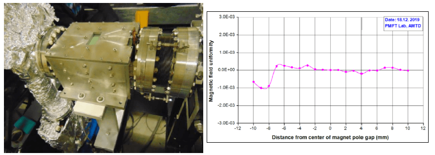
Fig. 99: Installed vertical pinger magnet in Indus-2 (L) and measured magnetic field uniformity along pole gap (R).
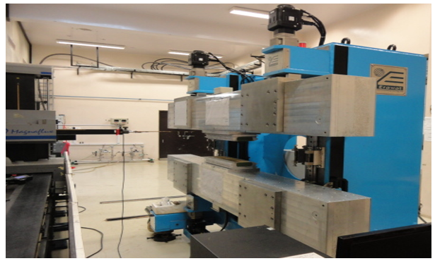
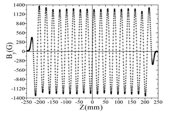
(iv) Development of a pre-prototype planar PM Undulator:
A pre-prototype planar permanent magnet (PM) Undulator of length ~ 500 mm with 56 mm period has been developed. High field NdFeB PM blocks have been mounted precisely on the two horizontal jaws of the undulator structure is shown in fig. 100. Magnetic field measurement of the undulator was done and the measurement results meet the design specifications.
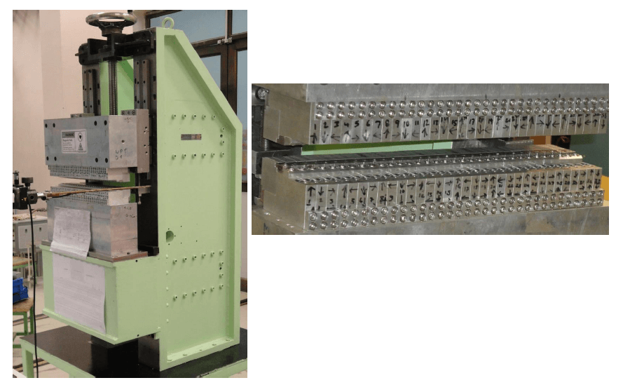
Fig. 100: Magnetic field measurement of pre-prototype Undulator with Hall sensor (L) and detail assembly view of PM blocks on the jaws (R).
(v) Development of a 2.5 m long prototype planar PM undulator:
The development of a 2.5 m long prototype permanent magnet (PM) planer undulator is in progress. This undulator has a mechanical support structure with two horizontal jaws on which an array of PM blocks will be assembled. These jaws require a precision vertical movement mechanism (drive system) in order to increase / decrease the gap (and so the magnetic field) from 5 mm to 200 mm between them. The gap drive system consists of servo motors, linear guides, encoders, limit switches, associated control electronics etc. The commissioning of the mechanical support structure with gap drive system for this undulator is in progress and is shown in fig. 101.
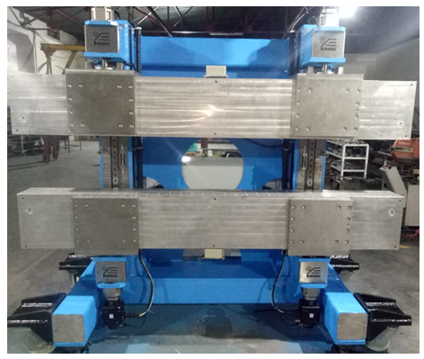
Fig. 101 : Mechanical support structure for a 2.5 m long prototype PM planer undulator.
(vi) Horizontal Pinger Magnet for Indus-2:
Pinger magnets (horizontal and vertical) are beam diagnostic tools for measuring various beam dynamical parameters of particle accelerators. In December 2021, a horizontal pinger magnet was designed, developed, characterized and installed in LS-4 of Indus-2 (fig. 102). The magnetic field pulse of the horizontal pinger magnet is half sine wave of width less than 1µs. The maximum field integral B.dl of the magnet is 130 Gauss-m. It will deflect the beam by 1.5 mrad in horizontal direction when energized by a sinusoidal current pulse of 2.7 kA peak. The pulse magnetic field uniformity along pole width and gap is better than 2 x 10⁻³.
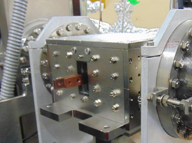
Fig:102: Horizontal pinger magnet installed in Indus-2
(vii) Development of combined function sextupole magnets for up-gradation of Indus-1:
A new set of eight combined function magnets with sextupole as main field component is required to improve the performance of the existing 450 MeV Indus-1 storage ring. Due to the space limitation, compact magnets are designed to incorporate auxiliary windings to generate skew quadrupole field and combined function (horizontal & vertical) dipole fields to control beam orbit. Skew quadrupole field reduces the coupling of the beam between two transverse planes. These combined function magnets have the nominal integrated sextupole field strength of 8.5 T/m and skew quadrupole field strength of 0.1 T besides horizontal and vertical steering kick strengths of each 2 mrad in both the planes. The aperture radius of these magnets is 50 mm and the overall length of 130 mm. All the eight magnets are successfully developed in which the magnet cores are made from soft iron plates and the coils fabricated from copper conductors. The magnetic measurements of these magnets were carried out using a rotating coil measurement system. The measured integrated strengths of various field components and their combined field quality of the magnets are as per the designed field quality requirements.
|
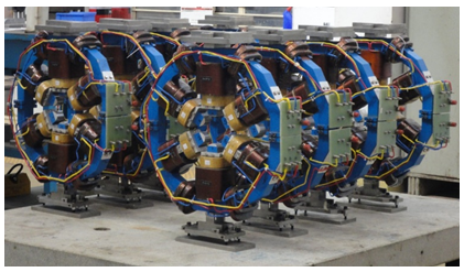
Fig.103: Series combined function magnets, showing various coils of sextupole fields, skew quadrupole, horizontal and vertical dipole fields.
|
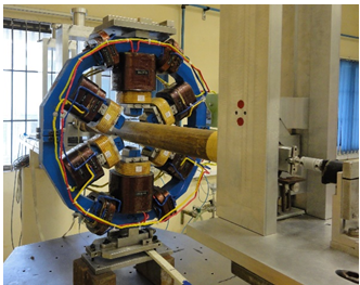
Fig:104: Magnet Characterization on the rotating coil bench
|
|
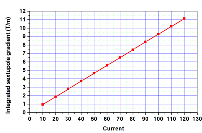
Fig:105: Integrated sextupole strength of magnet w.r.t its excitation current.
|
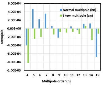
Fig:106: Integrated multipoles at r = 40 mm for only sextupole excitation at 100 A
|
Measured integrated strength of each field component for combined excitation in the magnet.
| Field component | Current (A) | Integrated strength at r=40 mm |
| Sextupole | 110 | 9.5 T/m |
| Skew QP | 10 | 0.133 T |
| Horizontal Steering | 10.5 | 3.1x10⁻³ T-m (> 2 mrad at 450 MeV) |
| Vertical Steering | 9.913 | 3.83x 10⁻³ T-m (> 2 mrad at 450 MeV) |
|