| Accelerator Magnet Technology Division |
|
2. Magnets developed for Indus Accelerators:
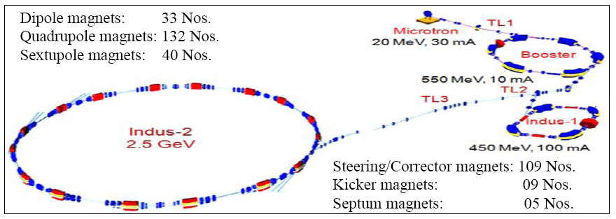
Fig. 23: Indus Accelerator Complex showing Booster Synchrotron, Indus -1 and Indus-2.
All the magnets required for the Booster Synchrotron, Indus -1 and Indus-2 storage rings and transfer lines (TL-1, TL-2 & TL-3) have been indigenously designed and developed by AMTD. The details of these magnets are shown below.
| S. No. |
TYPE OF MAGNETS |
STRENGTH
(B, g/k, Θ) |
QUANTITY (Numbers) |
| I |
TRANSFER LINE (TL – 1) MAGNETS |
| a) |
Quadrupole magnets |
2.5 m -2 |
06 |
|
b) |
150 Bending magnet |
0.075 T |
01 |
| c) |
Corrector dipole magnets |
± 5 to ± 10 mrad |
08 |
| II |
550 MeV BOOSTER SYNCHROTRON |
| a)
| Injection Septum magnet
| 0.22 T, 150
| 01 |
| b)
| Injection Kicker magnets
| 0.045 T, 20 mrad
| 03 |
| c)
| 600 Bending magnets
| 1.3 T
| 06 |
| d)
| Quadrupole magnets
| 8 T/m
| 12 |
| e)
| Corrector dipole magnets
| ± 2 mrad
| 06 |
| f)
| Extraction Septum magnet
| 0.877 T, 160
| 01 |
| g)
| Extraction Kicker magnet
| 0.08 T, 12 mrad
| 01 |
| III |
TRANSFER LINE (TL – 2) MAGNETS |
| a)
| Bending magnets
| 1.17 T / 0.75 T
| 02
|
| b)
| Quadrupole magnets
| 6 m -2
| 08
|
| c)
| Steering magnets
| ± 5 mrad
| 15
|
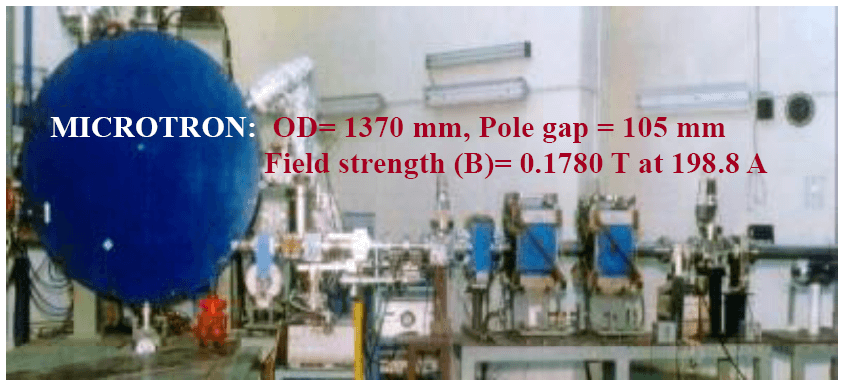
Fig. 24: Transfer line-1 magnets showing along with Microtron.
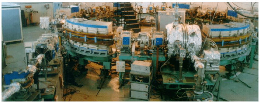
Fig. 25: 550 MeV Booster Synchrotron showing main dipole and quadrupole magnets and start of the transfer line -2.
Details of Indus-1 magnets.
| S. No. | TYPE OF MAGNETS | STRENGTH (B, g / k, Θ) | QUANTITY (Numbers) |
|---|
| IV | 450 MeV INDUS – 1 STORAGE RING MAGNETS |
|---|
| a) | Injection Septum magnet | 0.8377 T, 18. 30 | 01 |
| b) | Injection Kicker magnet | 0.08 T, 3 – 16 mrad | 01 |
| c) | 90o Bending magnets | 1.5 T | 04 |
| d) | Quadrupole magnets | 6 m -2 / 13.5 m -2 | 16 |
| e) | Sextupole magnets | 4 m -2 (k.l) | 08 |
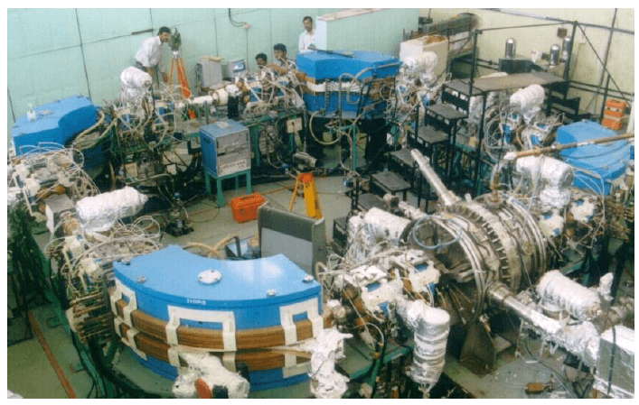
Fig. 26: 450 MeV Indus-1 storage ring showing main dipole and quadrupole magnets.
Details of transfer line -3 and Indus-2 magnets.
|
S. No.
|
TYPE OF MAGNETS
|
STRENGTH
(B, g / k, q)
|
QUANTITY
(Numbers)
|
|
V
|
TRANSFER LINE (TL –3) MAGNETS
|
|
a)
|
Quadrupole magnets
|
8 T/m
|
18
|
|
b)
|
Bending magnets
|
0.65 T
|
03
|
|
c)
|
Corrector dipole magnets
|
5 mrad
|
24
|
|
VI
|
2.5 GeV INDUS – 2 MAGNETS
|
|
a)
|
Thin Septum magnet
|
0.5 T, 20 & 30
|
01
|
|
b)
|
Thick Septum magnet
|
0.9 T, 190
|
01
|
|
c)
|
Kicker magnets
|
0.22 T, 25 mrad
|
04
|
|
d)
|
22.50 Bending magnets
|
1.5 T
|
16
|
|
e)
|
Quadrupole magnets
|
16 T/m
|
72
|
|
f)
|
Sextupole magnets
|
400 T/m2
|
32
|
|
g)
|
Corrector dipole magnets
|
1.3 mrad / 1.5 mrad
|
56
|
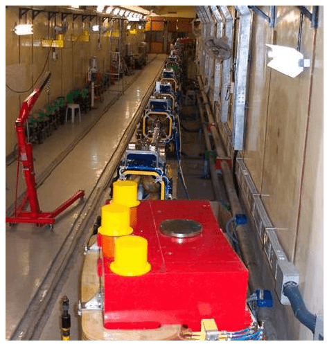
Fig. 27: Transfer line-3 showing main dipole and quadrupole magnets.
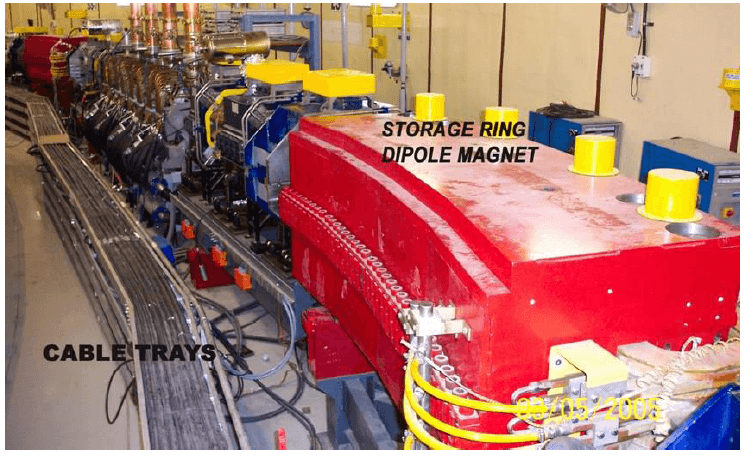
Fig. 28: 2.5 GeV Indus-2 storage ring showing main dipole and quadrupole magnets.
Details of magnets developed by AMTD
(i) Magnets for 2.5 GeV Indus-2 storage ring:
Dipole magnets: 16 Dipole magnets have been developed and deployed for Indus-2.
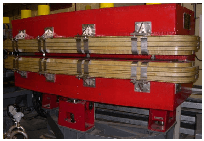
Fig. 29: Indus-2 Dipole magnet (Wt. ~ 10 MT) with support/positioning system.
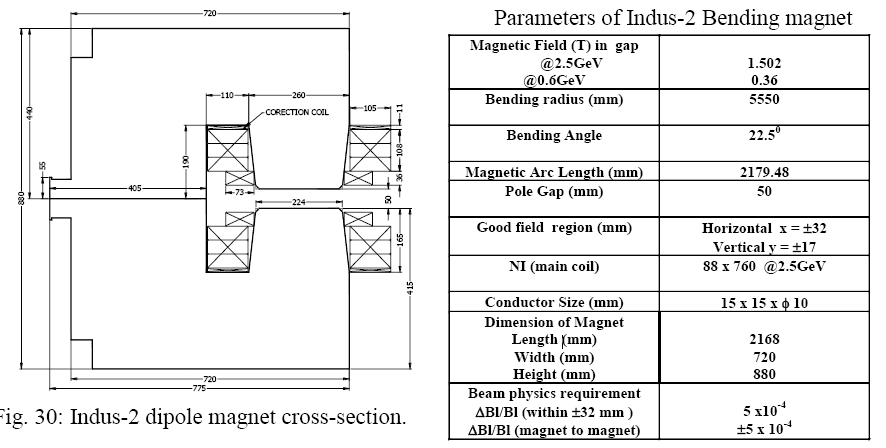
Fig. 30: Indus-2 dipole magnet cross-section.
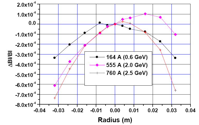
Fig. 31: Measured field quality of Indus-2 dipole magnet.
Quadrupole magnets: Total 72 Quadrupole magnets in five families (Q1, Q2, Q3, Q4 & Q5) have been developed and deployed for Indus-2.
Parameters of Indus-2 Quadrupole magnets.
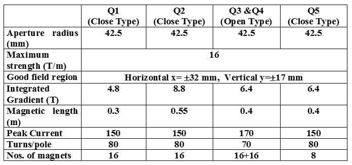
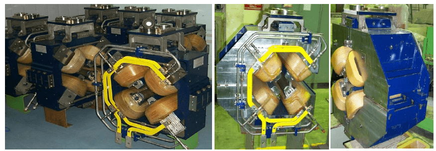
Fig. 32: Close-type quadrupole (Q1) magnets (L) & open-type quadrupole (Q3 & Q4)) magnets (R) of Indus-2.
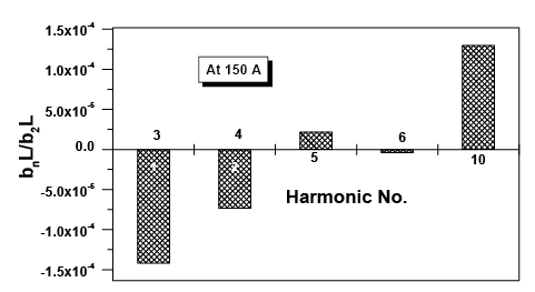
Fig. 33: Measured higher order harmonics of Q2 type Indus-2 quadrupole magnet.
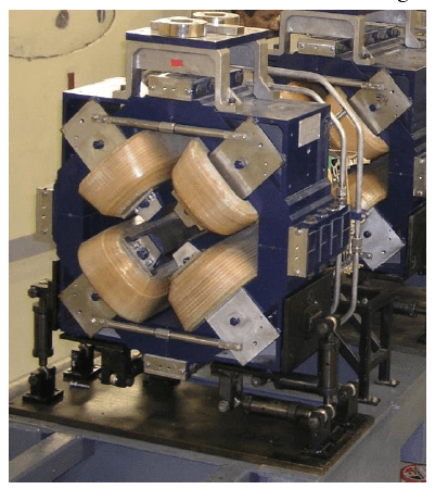
Fig. 34: Indus-2 quadrupole magnet (Wt. ~ 0.8 MT) with support/positioning system.
Sextupole magnets: Total 32 magnets have been developed and deployed for Indus-2.
Parameters of Indus-2 Sextupole magnets.
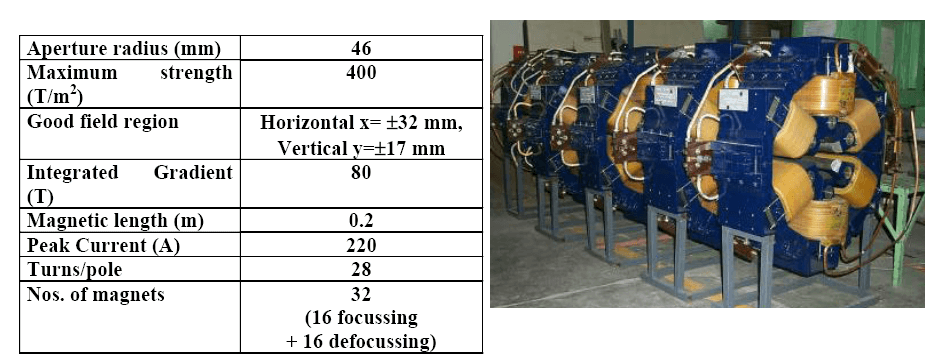
Fig. 35: Indus-2 sextupole magnets.
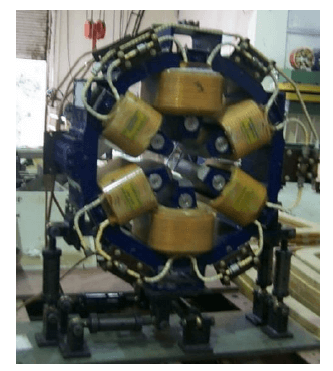
Fig. 36: Indus-2 sextupole magnet (Wt. ~ 0.6 MT) with support/positioning system.
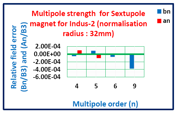
Fig. 37: Measured higher order harmonics of Indus-2 sextupole magnet
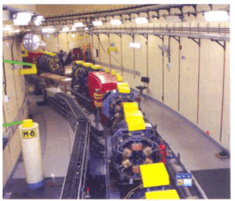
Fig. 38: Installed Sextupole magnets at Indus-2 storage ring along with other magnets.
(ii) Magnets developed for upgradation of 700 MeV Booster Synchrotron:
The existing booster magnets were made in the year 1990 and are working satisfactorily for acceleration of electron beam energy up to 550 MeV. The bonding between the glued laminations of the existing magnets has weakened over the period of time, thereby degrading its performance at 700 MeV. In order to operate the synchrotron at 700 MeV energy, new set of magnets have been developed with improved fabrication techniques and magnetic field quality. Also, the upgraded quadrupole magnets have been incorporated with auxiliary coils to generate the required sextupole (SP) magnet strength in the same aperture. The details of these magnets are given below:
Parameters of upgraded Booster Synchrotron Magnets.
|
Parameter
|
Dipole Magnet
|
Quadrupole Magnet
|
|
Field Strength / Gradient
|
0.037T @ 20 MeV
1.3 T@ 700 MeV
|
0.268 T/m @ 20 MeV
9.32T/m@ 700 MeV.
SP magnet gradient: 17.41 T/m2 at NI/coil of 644 AT.
|
|
Total Amp-turns
|
60,000
|
40,000
|
|
Pole gap/Aperture
|
52 mm at the centre
|
50 mm (Aperture radius)
|
|
Good field region
|
±40mm(horizontal)
±17 mm (vertical)
|
± 40 mm radius
|
|
Field uniformity
|
±0.05 %
|
±0.05 %
|
|
Effective length
|
1.88705 m
|
250 mm
|
|
Quantity in numbers
|
6
|
12
|
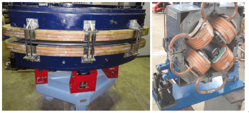
Fig. 39: Upgraded Booster Dipole (L) magnet (Wt. ~ 8 MT) and Quadrupole magnet with their support/positioning systems.
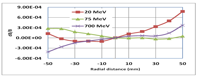
Fig. 40: Measured field quality of upgraded dipole magnet.
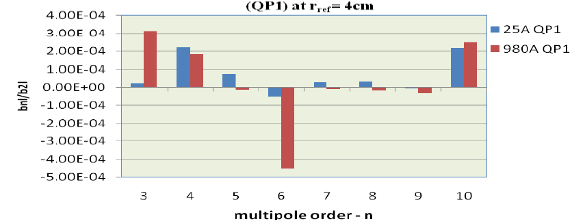
Fig. 41: Measured higher order harmonics of upgraded quadrupole magnet.
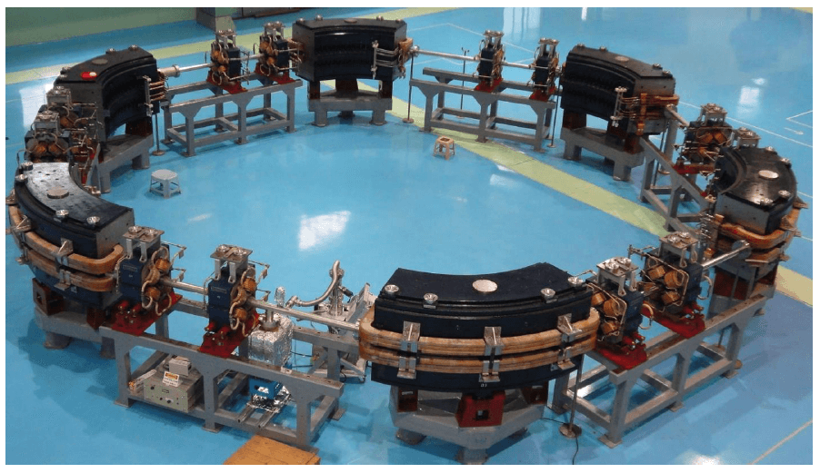
Fig. 42: Assembly of new Booster Synchrotron ring with upgraded main dipole and quadrupole magnets with their supports & positioning systems.
(iii) Magnets for beam transfer line of proposed 30 MeV Booster Linac:
A set of beam transfer line magnets (dipole, quadrupole, independent & combined function steering magnets) to connect new 20 - 30 MeV Injector Linac to the Booster Synchrotron have been designed and developed. The details of these magnets are given below:
Parameters of beam transfer line magnets for new 30 MeV Booster Injector Linac.
|
Parameter
|
Dipole magnets
|
Quadrupole magnets
|
Combined function steering magnets
|
|
(QP-80)
|
(QP-100)
|
|
Pole gap/Aperture
|
50 mm
|
80 mm Dia.
|
100 mm Dia.
|
94 mm
|
|
Peak field/Gradient
|
0.17 T
|
2.5 T/m
|
1 T/m
|
60 Gauss
|
|
NI/Pole in AT (Max.)
|
2640
|
960
|
3500
|
400
|
|
Bending angle
|
17°
|
--
|
--
|
± 6 mrad
|
|
Overall length
|
479 mm
|
236 mm
|
246 mm
|
100 mm
|
|
Quantity
|
1 No.
|
2 Nos.
|
4 Nos.
|
5 Nos.
|
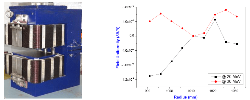
Fig. 43: Dipole magnet assembly (L) and its measured field uniformity (R).
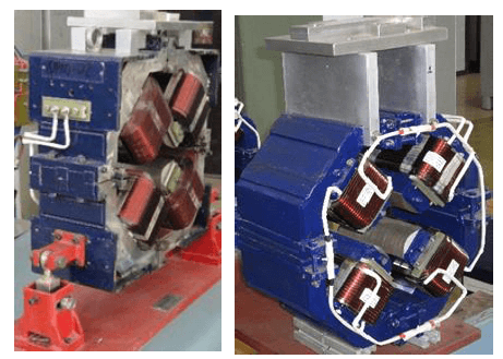
Fig. 44: Quadrupole magnet assemblies, QP-80 (L) and QP-100 (R).
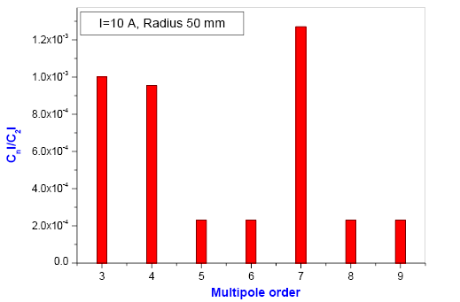
Fig. 45: Measured integrated higher order multipoles in QP-100.
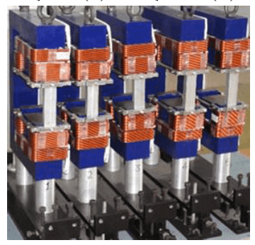
Fig. 46: Combined function steering magnets.
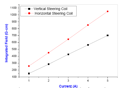
Fig. 47: Integrated field of steering magnets.
(iv) Pulsed magnets, FCTs and Hybrid magnets:
(1) Upgraded Septum and Kicker magnets for Indus Accelerators:
The upgraded septum magnets have been developed for 700 MeV Booster synchrotron, Indus-1 and Indus-2 storage rings for improved injection and extraction of electron beam. The magnet cores for these magnets have been developed from precisely cut 0.1 mm thick Ni-Fe laminations and the coils were machined from oxygen free copper plates & then alumina coated for providing the high voltage insulation. The measured field uniformity ( ΔB/B) in the upgraded magnets is < 5 x10⁻⁴ in their pole apertures and achieved the stray field of < 2 G-m.
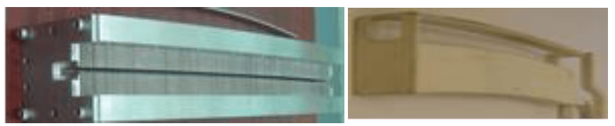
Fig. 48: Septum magnet core assembly 0.1 mm thick Ni-Fe laminations (L) and alumina coated copper coil (R).
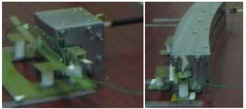
Fig. 49: Testing of the upgraded injection (L) and extraction septum magnets (R) for 700 MeV Booster Synchrotron.
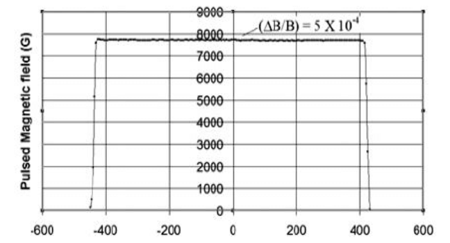
Fig. 50: Pulsed field uniformity along the beam path in the septum magnets.
(2) Upgraded injection septum magnets for Indus-2 storage ring:
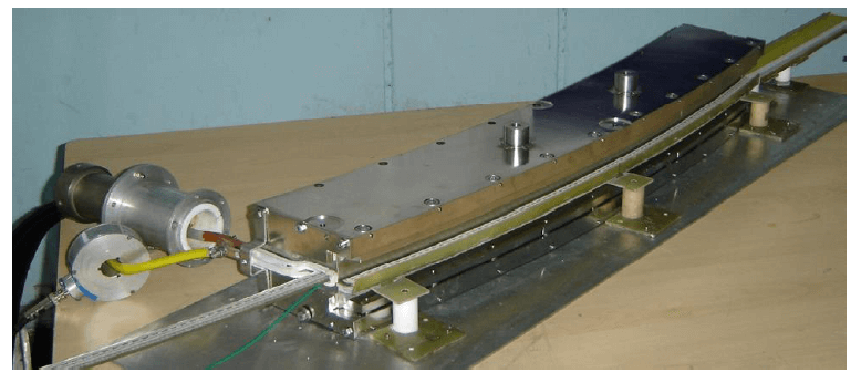
Fig. 51: Testing of upgraded thick septum magnet assembly for Indus-2.
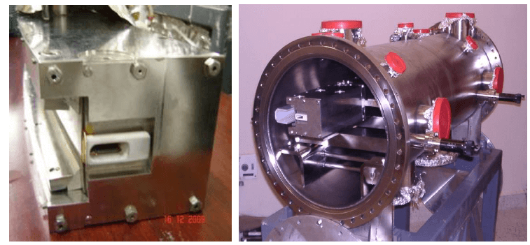
Fig. 52: New thin septum magnet for Indus-2 and its assembly in a vacuum chamber.
(3) Upgraded injection kicker magnets for Booster Synchrotron:
Total 03 Nos. of upgraded injection kicker magnets for Booster have been developed to inject the 20 MeV as well 30 MeV electron beam into Booster Synchrotron. It produces a pulsed magnetic field with a sinusoidal rise of 5 μs and a linear fall of 0.9 μs. The magnet cores of kicker magnets have been made using soft ferrites blocks and the coils from OF copper.
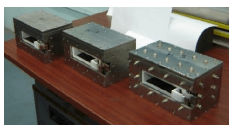
Fig. 53: Upgraded Booster injection kicker magnets.
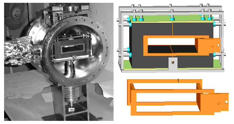
Fig. 54: Injection kicker magnet assembly, showing the soft ferrite core with copper coil.
(4) Prototype transmission line kicker magnet:
A prototype transmission line type fast kicker magnet has been developed with a view to extract all the three electron bunches from Booster Synchrotron. This kicker magnet has characteristic impedance of 25 ohms having split structure with multi-ferrite cells of low inductance.
The magnet is characterized with pulsar of 7 kV and 1.4 kA having current pulse of rise time of 45 ns and flat top of 80 ns. The achieved results are: (i) Rise time of magnetic field (full length): 53 ns (ii) Flat top ripple: 8% (iii) Propagation time of magnetic field through each module: 8 ns.
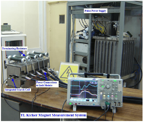
Fig. 55: Prototype transmission line type fast kicker magnet and its characterization.
5. Low coupling impedance kicker magnets for Indus-2:
Kicker magnets have been upgraded to reduce the coupling impedances. Two kicker magnets have been successfully developed by accommodating copper wire (0.5 mm dia.) loop in the magnet’s top and bottom ferrite yoke to provide secondary short to beam without affecting the quality of main deflecting magnetic field. The measured real and imaginary part of the longitudinal coupling impedance is less than 0.5 ohm and 20 ohms up to 300 MHz respectively.
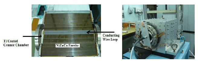
Fig. 56: Low coupling impedance kicker magnets for Indus-2.
6. Tunable hybrid magnet for biasing 505.8 MHz ferrite circulator:
A tunable hybrid magnet has been developed for biasing 505.8 MHz ferrite circulator of Indus - 2. The magnet system consists of strontium ferrite permanent magnet disks, pole pieces, excitation pole coils and magnetic yoke for completion of magnetic flux in the magnetic circuit. The magnet yoke and pole pieces have been fabricated from soft iron plates and the magnet has pole gap of 85 mm. In order to generate the required field of 1000 Gauss to 1500 Gauss in the magnet pole gap, two strontium ferrite permanent magnet disks (227 mm diameter x 25 mm thick) with one excitation coil on each pole have been used.
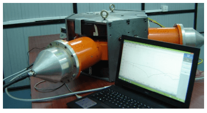
Fig. 57: Tunable hybrid magnet for 505.8 MHz ferrite circulator of Indus-2.
|
|


