|
1. Major in-house magnet development and testing facilities in AMTD:
I. General machinery available in AMTD for development of magnets as shown in fig.1.
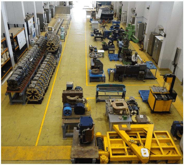
Fig. 1: General machinery for development of accelerator.
The general machinery available in AMTD include a lathe, radial drilling machine, vertical band saw, shearing machine, slitting machine, hand press, drilling cum milling machine, portable hand grinders, several inspection tools / gadgets etc.
II. Facilities for development of magnet coils:
(a) Winding machine for dipole magnet coils:
The machine has been utilized for winding of single/double pancake coils for dipole magnets. This machine has been equipped with low speed geared motor for rotation of winding fixtures, auto taping head for wrapping of insulation on the conductor, conductor straightening & tensioning unit etc. The details of the dipole winding machine is shown in fig.2 and fig.3 shows the encapsulated wound dipole coils with epoxy resin under vacuum.
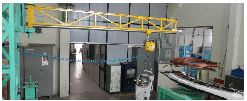
Fig.2: Dipole magnet coil winding machine.
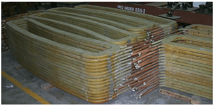
Fig.3: Epoxy-resin encapsulated Dipole magnet coils
(b) Winding machine for quadrupole and sextupole magnet coils:
This semi-automatic machine has been utilized for winding of race-track type coils with specified turns in various layers. The details of the quadrupole & sextupole winding machine is shown in fig.4 and fig.5 shows the epoxy-resin encapsulation plant and wound coils, epoxy resin encapsulated coils of quadrupole & sextupole magnets.
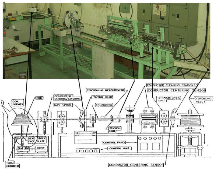
Fig. 4: Semi-automatic winding machine for coils of Quadrupole & Sextupole magnets.
(Main motor H.P: 2, Winding speed: 1 – 5 rpm, auto taping head & pitch adjustment)
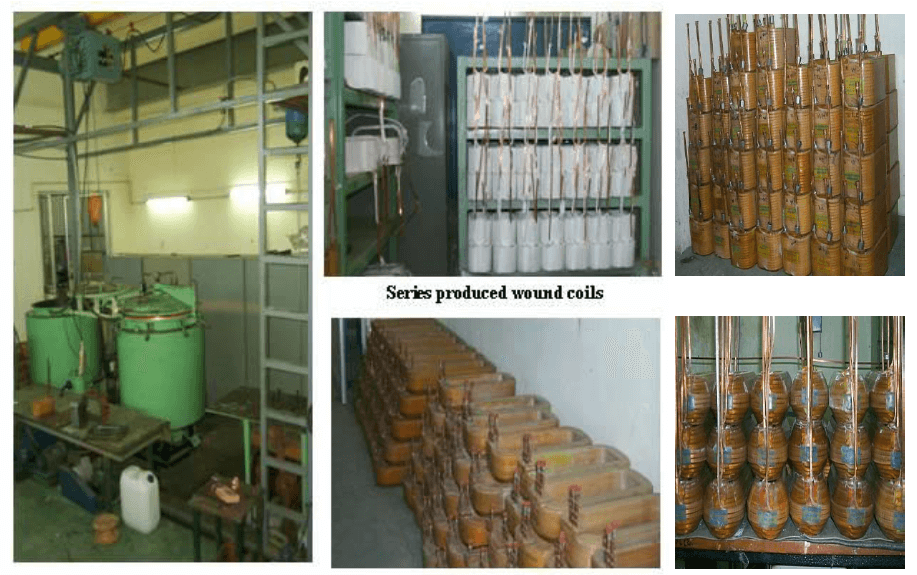
Fig.5: Epoxy-resin encapsulation plant (L), series produced wound and encapsulated coils of quadrupole & sextupole magnets (R).
(c) Magnet coil inspection facilities:
Several electrical testing gadgets (Fig. 6) have been developed for testing of fabricated magnet coils e.g. (i) Resistance & Inductance measurement gadgets for coils; (ii) Inter-turn coil insulation test set-up for checking of the coil insulation up to 1000 V. Also, a hydraulic-pneumatic test set-up (Fig. 7) for leak testing of water cooled magnet coils has been developed.
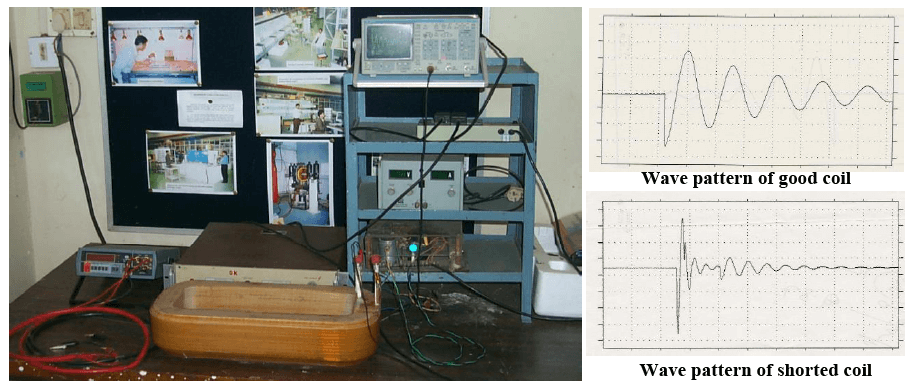
Fig. 6: Electrical testing gadgets for magnet coils, (i) Resistance & Inductance measurements;
(ii) Inter-turn coil insulation test.
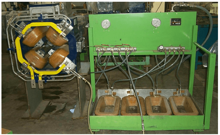
Fig. 7: Hydraulic-Pneumatic test set-up for water-cooled magnet coils.
III. LCW Plant:
A 700 kW, 650 LPM and 10 bar pressure low conductivity water (LCW) processing plant has been established in AMTD for cooling of high current density magnet coils during their testing. Fig. 8 shows the outside view of LCW plant and fig. 9 shows the details of inside process machinery for production of LCW.
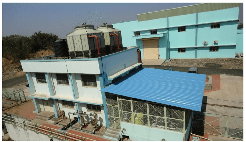
Fig. 8: Outside view of LCW plant installed & commissioned in AMTD.
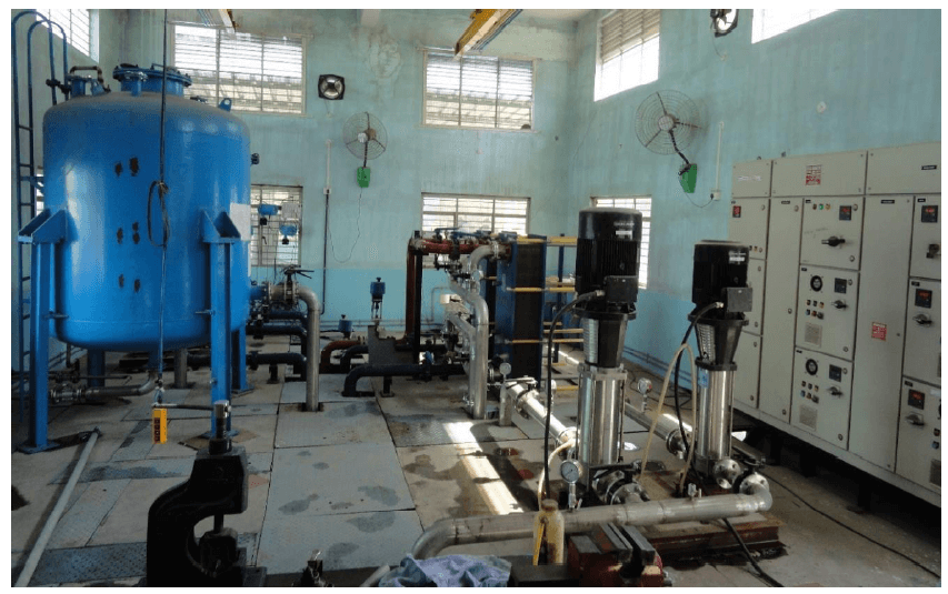
Fig.9: Process machinery inside plant for production of LCW.
Material handling facilities in AMTD:
Several material handling equipment (MHE) have been installed for handling of various magnets during their development. These include 1-2 MT jib cranes, mono rail cranes, 5-10 MT EOT cranes and a 50 MT EOT crane. The 50 MT (11.5 m span) is the highest capacity of EOT crane installed in RRCAT till to date. Fig. 10 shows the installed 50 MT EOT crane at MT Lab, AMTD for handling of large size electro-magnets.
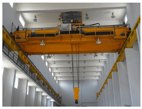
Fig. 10: 50 MT EOT Crane installation at MT Lab., AMTD
Magnetic field measurement facilities in AMTD:
(1) Hall probe based 3-D Magnaflux field mapping machine:
This has been developed mainly for field measurement of dipole magnets. The stroke lengths of the system in three orthogonal axes (X, Y & Z) are 3m x 0.8m x 0.6m respectively. The positional accuracy in all three axes is ± 0.01 mm / 1000 mm. The complete system is PC controlled with provision to operate it in manual mode through a joystick pendant and in auto-mode as programmed. The position and corresponding field values are acquired simultaneously for magnetic field analysis. Fig. 11 shows the details of 3-D Magnaflux field mapping machine.
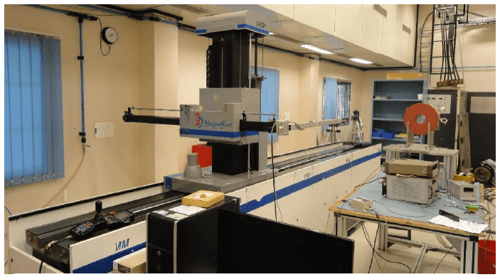
Fig. 11: 3-D Magnaflux field mapping machine for dipole magnets.
(2) Rotating coil multipole measurement system:
A large aperture rotating coil measurement system (Harmonic bench model 692, supplied by M/s. Danfysik, Denmark) has been installed/commissioned for measurement of harmonics in multipole magnets (quadrupole, sextupole magnets etc.) of weight up to 7 tons. This bench has the measurement accuracies in integrated main harmonics of ± 3x10⁻⁴ and of ratios between integrated fields of multipole components with main component at the major coil radius of ± 3x10⁻⁴. Fig. 12 shows the rotating coil multipole measurement system with a large aperture (dia.: 310 mm) quadrupole magnet.
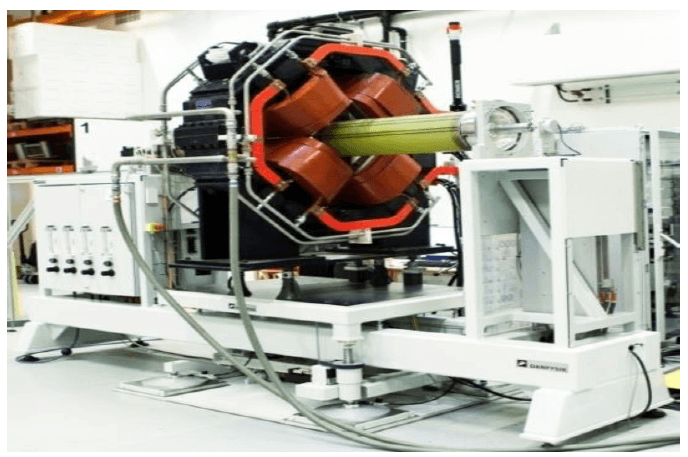
Fig. 12: Rotating coil measurement system (Danfysik make) with quadrupole magnet.
(3) Indigenous rotating coil multipole measurement system:
A rotating coil based magnetic measurement system has been successfully developed in-house for characterization of multipole magnets. The measurement system is shown in fig. 13, comprises of a rotating coil, a dc motor to rotate coil assembly, connected with an incremental encoder and a digital integrator (PDI-5025) for flux measurement. The measured higher order multipoles in a quadrupole magnet are found in good agreement with those obtained from the measurement system of M/s. Danfysik.
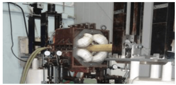
Fig. 13: Indigenous rotating coil measurement system with quadrupole magnet.
(4) Indigenous stretched wire measurement system:
A stretched wire system for the measurement of magnetic flux by moving a wire inside the DC magnetic field has been successfully developed in-house. This system comprises of a long wire loop, translation stages controlled by motors and a digital integrator for flux measurement. The measurement setup can be used to determine the magnetic axis of a solenoid magnet. The r.m.s repeatability of the measurement of the magnetic axis are found to ~ 0.2 mm for the centre and ~ 0.3 mrad for the angular orientation of the axis which are well within the limits typically specified for the solenoids used for the low energy Linacs.
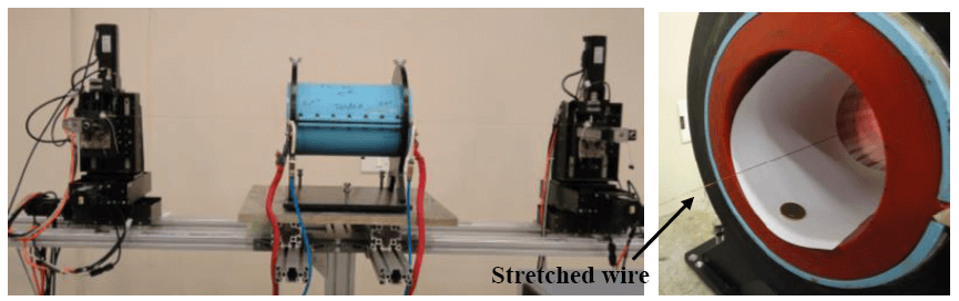
Fig. 14: Stretched wire measurement setup for measurement of the magnetic axis of a solenoid (L); Enlarged view of stretched wire passing through the aperture of the solenoid (R).
(5) 5 Tesla pulsed magnetizer for magnetization of permanent magnets:
A 5T pulse magnetizer system has been developed for the magnetization of large size ceramic and NdFeB magnets (90mm diameter). This is a capacitor discharge type magnetizer that generates a unidirectional pulse of magnetic field with a peak value of about 5T in the cylindrical fixture.
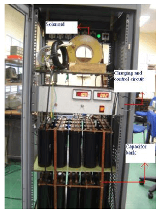
Fig. 15: 5T pulse magnetizer system.
(6) M-H loop tracer system for characterization of high energy rare earth magnets:
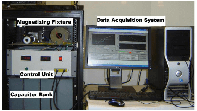
Fig. 16: M-H loop tracer system.
An M-H loop tracer has been developed using capacitor discharge method that generates a single period sinusoidal pulse of magnetic field with a peak value of about 5T in the cylindrical fixture. The system will be used to characterize NdFeB and Strontium Ferrite magnets (25mm diameter). For the characterization of permanent magnets, hard saturating field is applied before bringing the material in second quadrant and determine their remanence, coercive field and energy product.
(7) DC Permeameter for DC characterization of soft magnetic materials:
A DC Permeameter system has been developed for plotting DC B-H loop of soft magnetic materials at 0.05 Hz. The system holds dB/dt constant as low as 0.3 Tesla/sec which minimizes the error occurred in coercivity measurement.
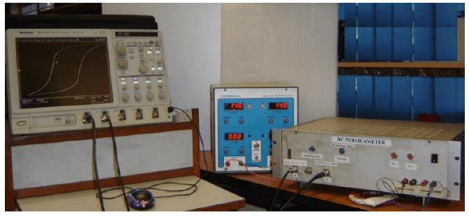
Fig. 17: DC Permeameter system.
Features of the instrument:
(i) Holds dB/dt constant which minimizes the error due to induced eddy current in low resistivity and high permeability test specimen.
(ii) Very low drift of integrating circuit over 20 second.
(8) Measurement set up for characterization of feebly magnetic materials:
A setup for measurement of magnetic susceptibilities of weak magnetic specimens has been developed. It is based on the measurement of magnetization in the sample, which is measured by compensated sensing coil and magnetizing solenoid. Principle of operation is based on the measurement of the magnetization (M) of the material under an increasing external field H.
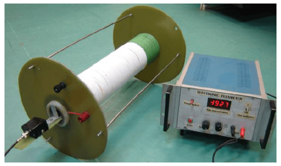
Fig. 18: Characterization of feebly magnetic materials.
(9) FMR Measurement setup using RF Sweeping technique:
A measurement setup has been developed based on a novel technique to measure the resonance line width, which uses discontinuity type coaxial line. The discontinuity type coaxial line is placed in the static magnetic field which is perpendicular to the RF magnetic field. The circular RF magnetic field and the applied static field excites the magnetization. When the RF coincides with the FMR frequency, the resonance appears which results maximum absorption of RF signal, which is measured by reflection.
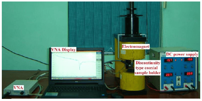
Fig. 19: FMR Measurement setup.
(10) Wide Band Complex Permeability Measurement set up
This measurement setup is based on transmission line techniques (Transmission/Reflection parameter based) so it can be used for wide frequency range, thus satisfying both the high frequency and wide band criteria of characterization.
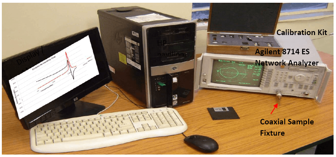
Fig. 20: Complex Permeability Measurement set up.
(11) Spin wave line width measurement system:
Spin wave line system has been developed for high peak power handling capability of garnets to be used in high power ferrite circulators. Developed systems also has been tested at low power in S band.

Fig. 21: Spin wave line width measurement system.
(12) Wide band ferromagnetic resonance measurement system:
The wide band resonance line width measurement system uses flared coaxial fixture which is excited on one side and short circuited termination on form of load. This fixture is placed over external DC magnetic field, which act as DC magnetic biasing of the ferrite sample, in direction perpendicular to RF magnetic field.
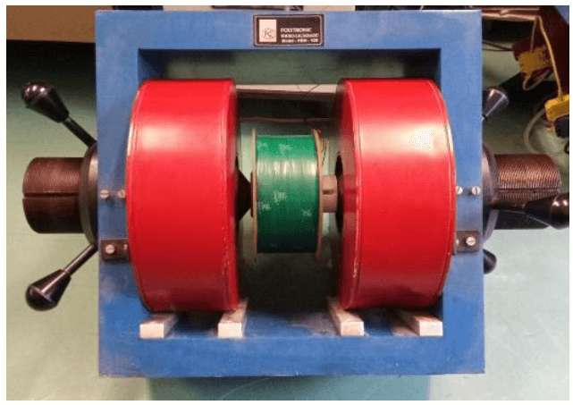
Fig. 22: Ferromagnetic resonance measurement system.
(13) Ferrite development facilities: The following facilities are available in PMFT Lab for development of ferrites:
| Planetary ball mills. |
Presses. |
| Furnaces (sintering and hydrogen annealing furnaces). |
Microwave digestion system. |
| Lapping and polishing machine. |
Precision slicing machine. |
|
Surface grinding machine. |
Thermal spray alumina coating system. |
(14) Helmholtz coil measurement system for characterization of permanent magnet blocks
The majority of insertion devices used in synchrotron light source are undulators. Undulators are build using permanent magnet blocks like Samarium Cobalt and Neodymium Iron Boron. The magnetic field quality of an undulator is related to the variation of magnetic properties of the individual permanent magnet block. Therefore, the magnetic properties of each block should be measured precisely and accordingly sorted before being used in the assembly of undulator to minimize the field integrals and the phase error of the device. A Helmholtz Coil measurement set up has been developed to characterize the permanent magnet blocks. Fig.23 shows the Helmholtz coil setup. The measuring system consists of two identical circular coils of radius 400 mm placed coaxially and separated by a distance equal to the radius of the coils. The number of turns for each coil is 3000. A vertical rotary mechanical system with aluminum shaft with a magnet holder, which holds the magnet in the centre region of the coil pair.
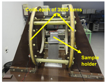
Fig. 24: Helmholtz Coil setup for characterization of permanent magnet block.
The rotation of the sample by a motorized mechanism with encoder connected induces the voltages in the coil. The resolution of digital encoder is ~0.0220. The integrated voltage (flux) is sampled by a digital integrator (PDI-5025). The DC motor, digital encoder and the integrator are interfaced with a PC. Fig. 24 shows the GUI developed for control and data acquisition for the measurement setup.
A repeated measurement of an NdFeB permanent magnet block yields the repeatability of the total strength of the magnetic moment and angular orientations of the components of magnetic moment w.r.t. the total moment well below 0.1 % and 0.10 degree respectively.
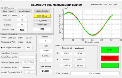
Fig. 24: Snapshot of GUI for Helmholtz Coil setup.
(15) Augmentation of indigenous rotating coil multipole measurement system:
Recently, the existing multipole measurement system has been successfully equipped with a motorised multi-axes precise magnet positioning system for alignment of the multipole magnets during their magnetic field measurements. This positioning system has a load carrying capacity of 10 kN and range of motions include linear motion of ± 25 mm and rotational motion ± 3 degree. The positional accuracy of the positioning system is ± 0.02 mm in linear and ± 0.1 mrad in rotational on X, Y and Z - axes.
This indigenously developed complete measurement system is shown in fig. 23. It consists of a rotating coil, a dc motor to rotate the sensor coils assembly, an incremental encoder and a digital integrator (PDI-5025) for flux measurement. The measured higher order multipoles in a multipole magnet eg. a quadrupole magnet or a sextupole magnet are found in good agreement with those obtained from the measurement system of M/s. Danfysik.
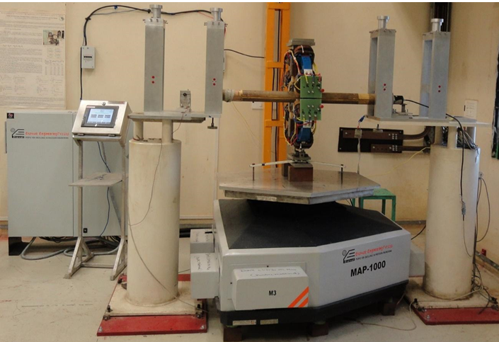
Fig.25: Indigenous rotating coil measurement system with magnet positioning system measuring sextupole magnet
|


