Indigenous developments and Cryogenic infrastructure
Cryogenics technology as an enabling technology for high power accelerator and cutting-edge research. The section is responsible for the in-house design and development of indigenous systems and day to day operation of large cryogenic systems extensively built for testing of next generation of accelerator components. Main Cryogenics section activities are listed below.
Indigenous Developmental Activities:
- Helium liquefier
- Cryocoolers
- Cryostat
- Cryopump
Cryogenic Infrastructure and Facilities
- Cryogenics Section Infrastructure
- Cryogenics Facility
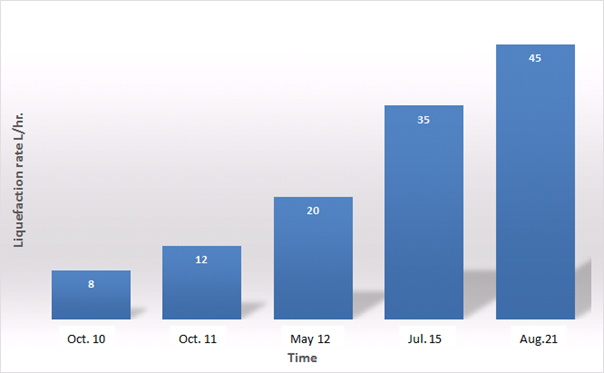
Helium is a material of strategic significance, and its liquid temperature range almost extend to absolute zero. On August 14, 2010 at 21:15 hrs, we achieved Helium liquefaction in fully indigenously designed and developed system for the first time. This helium liquefier system was based on reciprocating type expansion engines and shell and tube heat exchangers both designed and built in-house. Since than the production rate of this system is continuously improved from modest 6 L/ hr. to the present 45 L/hr. through constant design improvement and technical upgradation. This increase in the liquid helium production rate over the years have been depicted in the figure 1.
Helium liquefiers basically comprises of following components: active refrigeration producing expansion devices with work extraction mechanism, a train of efficient heat exchangers, pressure regulating valves, temperature and pressure measurement sensors all housed in a vacuum insulated chamber with multilayer insulation called cold-box.
Helium liquefier system developed by us has two reciprocating type expansion engines operating at 50 and 20 Kelvin respectively. These expansion engines consist of protracted fibre reinforced plastic expanders housed in stainless-steel liners. Fibre reinforced plastic has somewhat similar thermal expansion and contraction when compared with stainless-steel and their extended length results in reduction of heat in leaks from environment temperature to the expansion space that is typically operate at extreme low temperature. For our helium liquefier locally made fibre reinforced plastic pistons are used for the manufacturing of expander displacer. Due to these extended lengthy expanders, the expansion process takes place deep inside the cold box, whereas other components of expansion engines such as fly wheel, inlet and exhaust valve actuators, work extraction mechanism that includes braking mechanism, etc. operates at room temperature.
The gaps between the piston and liner, called “void volume”, plays a significant role in achieving the required expansion efficiency. The maximum allowable void volume to have very good efficiency should be less than approximately 4% of the total volume. Cryogenic valves, one of the critical components of the expansion engine are also developed in-house and currently extensively used in the other cryogenic application with slight modifications. For the work extraction, standard automobile alternator is used with few internal modifications to suit the requirements. Speed of the reciprocating expansion engines are regulated by varying power supply of the alternator stator coil.
Expansion engine-based system have an advantage of having larger temperature drop due to their ability to work at higher pressure ratios. Turbine based system normally has small expansion ratio and consequently small temperature drop. To achieve same refrigeration effect turbine type system requires higher flow rates consequently their size of the heat exchangers is larger as compared to the expansion engines-based system. Six numbers of aluminium plate fin heat exchangers used in system are specifically developed as per our design specifications by an Indian vendor. More detail about the first heat exchanger working in the range of 300 K to 80 K can be found at following web page.
https://www.sciencedirect.com/science/article/pii/S1359431116304057.
After passing through series of heat exchangers and intermediating cooling by the cryo-expanders high pressure helium gas finally cooled down to about 7 K or lower and then enters Joule Thomson (JT) expansion valve. On expansion through JT valve, a fraction of the flow converts to Helium mist. The quantity of Helium mist fraction depends on the inlet temperature and pressure of helium gas at the entrance of JT valve and its final pressure after its expansion. The JT valve for the system was designed, calibrated and its fabricated was entirely performed in-house. The amount helium mist that is effectively condense as liquid Helium in the Dewar or helium storage vessel, strongly depends on the stability of pressure inside the Dewar. Achieving and collecting substantial amount of liquid helium also implies the stable pressure and temperature conditions shall be maintained over the period time extending to a few days.
The other deciding factor for operation extended over long period, are the handling of impurities in high pressure helium gas stream, especially oil carry over from main/recycled process compressor. An efficient oil removal system has to be employed for this purpose. The oil removal system is also designed by us and fabricated by local fabricators. In addition to its design and fabrication, processing of helium flow thru several intermediate components plays an important role in it. Locally available activated charcoal has been used in our system and its processing parameters were also established. Standard oil coalescing filters are used in this system.
The main process compressor, which maintains supply of pure oil free high-pressure helium gas at about 230 psig and return low pressure of about 2 psig, was procured from Indian manufacturer. This reciprocating compressor system, Model No. C4U217.4G, is belt driven, oil lubricated, four stages with air cooled intercooler and supplied by M/s Sulzer India Ltd. To handle the helium high heat of compression, manufacturer has suitably modified the compressor system for additional cooling. To avoid air in-leaks in the compressor during suction cycle, minor alterations were done in the process circuit of the compressor by us, after its commissioning at RRCAT.
Several noteworthy improvements were carried out to increase the liquefaction rate of first version to the next version of liquefier by adding liquid nitrogen precooling stage, larger size multi-streams finned tube in shell heat exchangers and their optimization at different process parameters. With these changes the we could manage to increase liquefaction rate of liquefier to 20 L/hr. Due to limitation of finned tube in shell type heat exchangers in handling larger helium gas flow and refrigeration produced by the expansion engines further enhancement in liquefaction yield was not possible in that system.
To further enhance the liquefaction rate, new reciprocating type cryogenic expansion engines with larger refrigeration capacity were designed and fabricated. State of the art brazed aluminium plate fin heat exchangers with high heat transfer rate, effectiveness, compactness and having pressure drop in range of tenths of millibar were developed through an Indian vendor. First brazed aluminium plate fin heat exchanger built by the vendor for temperature range 300 K to 80 K was integrated with the newly built reciprocating type expansion engines. This system was developed using brazed aluminium plate fin heat exchanger up to 80 K whereas below 80 K finned tube in shell type heat exchangers were integrated after suitably matching their thermal characteristics. As over the past few years, the liquefication capacity of system has increase many folds, to meet the additional helium flow requirement Kaeser make Model No. CDS102 has been added in parallel. With all these above-mentioned modifications the liquefier was operated, its cooldown performance at the inlet of JT valve is shown in figure 2.
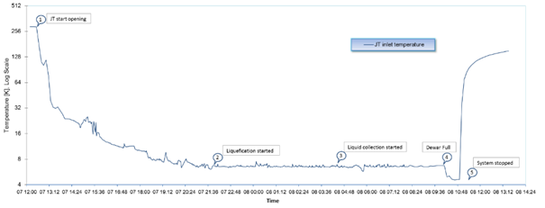
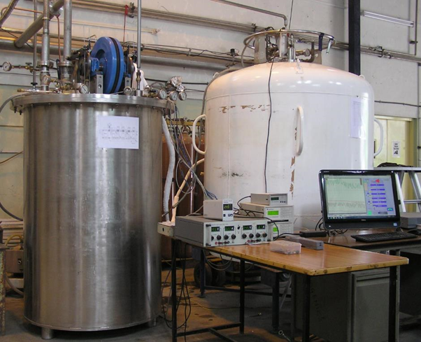
This JT inlet temperature profile show the liquefier cooldown performance along with 250 litre capacity main Dewar. As both the transfer line and Dewar were at room temperature, point 1 show the temperature of JT inlet before its opening. After that JT valve was opened and the cold end of the system started to cool down. After an interval of few hours JT inlet temperature reached at a temperature were helium mist formation is started inside the main Dewar of the system and as shown by point 2. Actual liquid helium collecting in the Dewar is started at point 3 and could be verify through liquid Helium level gauge. After about five hours of stable operation Dewar became full and liquid started flowing back through the return line. This brought down the JT inlet temperature near to 4.5 K, as shown by point 4. Helium plant was shut down at point 5. At this point, system demonstrated a liquefaction capacity of more than 35 L/hr. During its subsequent trial runs the liquefier was integrated with one thousand litre Helium Dewar. Figure 3 shows the photograph of indigenous helium liquefier with prominently visible Dewar of 1000 litre liquid helium capacity.
The current version of this liquefier system was further upgraded with all heat exchangers changed to brazed aluminium plate fin heat exchangers. All these high efficiencies brazed aluminium plate fin heat exchanger were manufactured in India. This was first time in the country when all such heat exchangers were successfully deployed in a helium liquefaction system. With large capacity expanders, cryogenic valves and state of art six numbers of brazed aluminium plate fin heat exchangers, our liquefaction yield has touched approximately 45 L/hr. in the current version of indigenous helium liquefier.
Presently the cold end section of liquefier system has been modified to mitigate excessive flash-off losses. With this completely new design of liquid helium transfer scheme and cold helium vapor management and especially cooling of Dewar from the environment temperature to final liquefication temperature will became more efficient.
Feed Helium gas used are generally recovered form user experiments and is an expensive consumable. Its conservation is important not only for saving on cost, but also for ensuring continuous supply to the various ongoing experiments. Recovered helium gas is often contaminated with air impurities such as Nitrogen, Oxygen, Argon, moisture and traces of oil etc. which must be completely removed before this recovered helium is feed for liquefaction. Therefore, it necessitates use of integral helium purifier system in the helium liquefication system to conserve helium. The design of integral helium purifier is in its advance stage and we hope to integrate it in the very near future.
We sincerely acknowledge our gratitude toward all the members of Cryogenic team for the constant upgradation and upkeeping of this indigenous system.
Development of 4K, 10K and 30K class Cryocoolers
We have indigenously developed two types of single and double-stage Gifford McMahon type cryocooler for relatively cold temperatures (30 K, 10 K & 4 Kelvin) applications. Cryocoolers like domestic refrigerator requires only electricity to produce low temperature. Our designed and developed cryocoolers can generate a minimum temperature 30 K in a single-stage and 10K & 4 K in a two-stage unit. Cryo coolers are efficient way to conduct ultra-low temperature experiments, cutting down on the bulk of the traditional cooling infrastructure needed for this technology. The entire cryocoolers are made of indigenously available components.
The Cryocooler consist of two major modules, an expander and a compressor module. The cryocooler uses Helium gas as working fluid. Helium being monoatomic gas, its isobaric to isochoric specific heat ratio gamma is 1.67 (g = cp/cv). Helium produces large amount of heat during its compression, therefore conventional compressors available for CFC or hydro-carbons with g ranging between l and 1.3 in the open market cannot be used. For the compression of Helium gas in conventional compressor, additional oil is injected in the helium flow at the level of the compressor suction to protect the damage to the compressor valves and to avoid cracking of the lubricant. This additional oil act as a thermal moderator during compression and keep the temperature of compressor in acceptable limits. Most of this oil is later removed from the compressed helium gas by centrifugation and coalescence techniques. The remaining traces of a few parts per million are trapped in iron powder bed with an activated charcoal adsorber trap. The compression module is connected to the expander module having cold finger for the experimentation by high and low-pressure flexible lines, allowing for a separation of both sub-systems without any noticeable efficiency loss. Compressor for use in the above cryocooler has been developed at RRCAT by the modification of conventional compressors, used in conventional air conditioning, along with an on-line oil injection and removal system.
Cryocoolers have unique role in applications with small heat load requirements for temperature range below the boiling point of liquid Nitrogen i.e. under 77 K. They are also widely use as Cryogen-free system to mitigate large infrastructure requirement for cryogenic system. They are popular because of their simplicity and high reliability. They offer very large mean time between failure, thus provide continuous uninterrupted cooling for very long operating periods. Developed cryocooler were subjected to rigorous testing in term of their repeated performance. Both types of cryocoolers were given to the various laboratory for the field trails. Cryocoolers developed by us are being used by different user labs at RRCAT.
These cryocoolers are being used with following setups:
- Materials, Advanced Accelerator Science Div.: Working over a wide temperature range (30-400K), capable of precision measurements of phase transition phenomenon in magnetic materials and superconductors.
- Semiconductor Laser Section: Temperature Dependent Electrical Transport measurements on semiconductors thin films and optoelectronic structures like lasers, detectors – Regularly grown using MOVPE system at RRCAT.
- Laser Physics Applications Division: Temperature Dependent Carrier Dynamics measurements by Ultra-Fast Pump Probe Spectroscopy.
- Photoluminescence setup at BARC Spectroscopy Lab RRCAT Indore: Cryocooler is coupled to a spectrofluorometer of Jobin-Vyon (Model no- Fluoromax-3) suitable for experiments in Temperature range of 40 to 300K.
- Laser Physics Applications Division: Temperature Dependent Transient Photoconductivity & Photoluminescence of Organic Semiconductors.
- Materials, Advanced Accelerator Science Div.: Resistivity versus Temperature measurements.
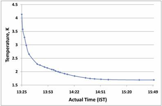
A pool type liquid Helium cryostat for operating very near to absolute zero Kelvin was designed, fabricated and successfully commissioned for the calibration of Cernox sensors. In this, the temperature of liquid helium, which has a normal boiling point of 4.2K is brought down further by pumping over the liquid. This system operates under sub-atmospheric conditions. Apart from efficient thermal design to minimize heat in-leaks through different mechanisms, there are several technical issues which are required to be tackled in making a cryostat of this type.
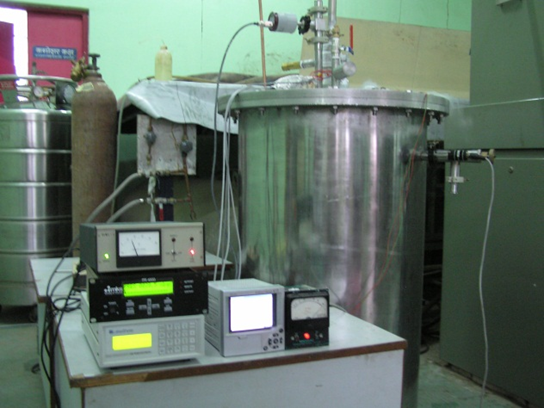
This cryostat was fabricated by a local fabricator. It was first tested at normal liquid helium temperature (4.2K). Heat in-leak calculated from the boil-off was less than 70 mW. These values of heat in-leak, match closely with the values reached during the designed stage. 2K temperature can be reach in about 36 min after starting the evacuation pump at 4.2 K. Cryostat has capacity of about 08 litres of liquid helium at 4.2 K, and after pumping when it reaches 2K temperature, it still left with about 4.5 litres of superfluid helium. After reaching 2 Kelvin temperature, the helium boil-off losses are quite low for cooling from 2 K to 1.7 K, as the self-heat load of the cryostat to the 2 K liquid chamber is fairly low. It takes about ½ litres of liquid to maintain 1.7 K in the cryostat for an hour. This cryostat is now extensively used for the calibration of cryogenics temperature sensors in 4.2 to 1.7 K range.
Development of Cryopump:
Modern high-tech electronic products increasingly demand a ultra-clean vacuum, free from of hydro-carbons. At very low temperatures of around 10 K, most of the gases condense and this property is used to produce ultra-clean vacuum using cryocooler operated cryopumps. The cryopump is a gas-condensing vacuum pump which is preferably employed in the pressure range from 10-2 to 10-10 mbar. The cryo-pump pumping effect is based on the fact that the gases which need to be pumped condense inside the pump on sufficiently cold surfaces. RRCAT has successfully developed a proto type cryopump having pumping speed of 1,200 L/sec. and producing an ultimate vacuum of 10−8 mbar using 2-stage GM Cryocooler developed by us.
|


