| FEL & Utilization Section |
 FEL & Utilization Section
Design & development of an infrared Free Electron Laser (IR-FEL)
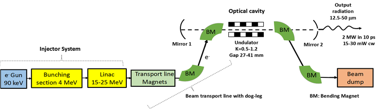
An Infra-Red Free Electron Laser (IR-FEL), designed to lase in the 12.5 - 50 μm wavelength band has been built and commissioned at RRCAT. A schematic of the IR-FEL is shown below in Fig.1, and Fig. 2 shows a picture of the IR-FEL installed inside a 60 m [L] x 5 m [W] radiation shielded area. After achieving saturation of lasing in 2019, it has been operated regularly for FEL optimization experiments leading to repeatable operation of the machine with a measured Continuous Wave (CW) average out-coupled power ~ 25 mW at 21.8 mm wavelength for 2 Hz Pulse Repetition Rate (PRR). This translates to a Spectral Brightness ~ 2.1 x 10¹⁴ photons/s/mm2/mrad2/0.1% BW. The peak out-coupled power in these experiments is estimated to be > 7 MW in 10 ps FWHM pulses.
Wavelength tunability of the FEL radiation from 12.5 - 40 mm wavelength has been achieved, and extension of the operating wavelength up to 50 μm will be achieved in the near future after a planned upgrade of the undulator vacuum chamber. Operation of the IR-FEL with > 60 mW CW average out-coupled power has also been demonstrated by increasing the PRR of the machine.
IR radiation from the FEL has been transported from the radiation shielded vault up to the user area over a distance > 50 m through a pressurized (dry Nitrogen) optical beam transport line employing 21 gold coated copper mirrors of average power reflectivity ~ 0.95. Beam matching stations have been employed at the two ends of the optical beam transport line for efficient transport. Figure 3 shows a picture of the measured IR power of 5 mW in the diagnostic room in the user area at a wavelength of 21.8 µm. To continuously monitor lasing of the IR-FEL, a fraction ~15% of the out-coupled power from the FEL is sampled using a KRS-5 beam splitter inside the IR-FEL radiation shielded area, while the remaining 85% is sent to the user area. Figure 4 shows a typical measured stability of the sampled FEL power over a six-hour operation cycle.
A typical 2D and 3D transverse optical profile measured at the user room, measured using a Pyrocam, is given in Fig. 5. Characterization of the FEL radiation in the user area has been performed by studying its transverse mode profile using a Pyrocam, transient and saturated power profiles using a fast detector (MCdTe), and through the study of the transmission spectra of a standard sample using the FEL radiation as well as on a Fourier Transform Spectrometer.
IR-FEL light is presently being delivered to the FEL user facility for detailed characterization and trial experiments.
|
Figure 1: Schematic of the IR- FEL at RRCAT Indore, India. |
|
Figure 2: Shows the IR-FEL setup installed inside the radiation shielded area [60 m L x 5 m W x 3.5 m H] |
|
Figure 3: The CW average power measured at diagnostic room in user area. |
|
Figure 4: Typical stability of the sampled out-coupled power. |
|
Figure 5: The 2D (L) and 3D (R) mode profile on Pyrocam (R) measured at user room. |
|
|
|
|