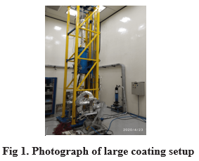
- Large Coating Setup
A vertically oriented large coating setup (LCS) with overall size of 1300 mm x 1200 mm x 5500 mm height was indigenously developed, installed and commissioned in UHV Lab in 2017. This coating system, based on DC magnetron sputtering technique, will be used for NEG film coating of long UHV chambers required for undulators in Indus-2 and future high brilliance storage ring for UHV pumping requirement and TiN coating of vacuum chambers of accumulator ring of future Indian Facility for Spallation Research (IFSR) for low secondary electron yield (SEY) requirement. Vacuum chambers with cross section dimension up to external diameter 290 mm and length up to 3500 mm can be accommodated for coating in this set up. Various sub-systems of this coating setup are: custom built motorized solenoid lift of 3750 mm stroke height, all metal bakeable vacuum system, gas (Ar/Kr) dosing system with inline gas purifier, water cooled solenoids of inner diameter 360 mm / 250 mm x 1000 mm length, power converter: 250 A / 50 V DC for solenoids, high voltage DC power supply: 2 kV / 6 A for gas discharge, water chiller, PC based bake out & NEG activation controller and data acquisition system for in-situ bake out & NEG coating activation and acquisition of process parameters. Motorized solenoid lift consists of precision lead screw mechanism which provides linear speed of 300 mm/minute (bi-directional) to solenoid. All metal bakeable vacuum system consists of 270 l/s SIP, UHV gauge and RGA. Photograph of the large coating setup is shown in Figure-1.
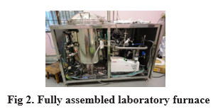
- Advanced Laboratory Furnace
A fully integrated computer controlled 40 kW advanced laboratory furnace with state of art dynamic argon (Ar) partial pressure system was installed and commissioned in ultra-high vacuum (UHV) lab (Figure 2.). The laboratory furnace is used for conducting brazing experiments either in vacuum or Ar partial pressure atmosphere for optimizing brazing process parameters (filler material, joint design, electroplating requirements, brazing temperature, soaking time and partial pressure of Ar) for development of recipe of UHV compatible brazed joints involving advanced materials such as OFE Cu, ODS Cu, Be-Cu, Be, Nb, SS, Ti and Ti alloys and high purity alumina ceramics used for particle accelerators.
Salient features of the laboratory furnace are given in Table-1. The furnace is designed to operate in hydrocarbon free high vacuum (~5×10⁻⁷ mbar) as well as argon (1×10⁻³ to 1 mbar) atmosphere. The furnace consists of Ar purifier system which provides dew point <65ºC, to facilitate enhancement of brazeability of metals by minimizing the oxide formation due to water vapour.
Design, construction, testing, installation and commissioning of the lab furnace was based on "NFPA-86D Standard for Industrial Furnaces using Vacuum as an Atmosphere 1999 Edition". Temperature uniformity survey of the furnace was carried out conforming to AMS 2750D standard.
The laboratory furnace is equipped with state of art SCADA control system architecture that uses HMI, GUI for high-level multi process supervisory control. It is equipped with programmable logic controller (PLC) and discrete safety & PID standalone controllers to interface with various temperature, flow, level and vacuum parameters.
| Table-2. : Salient features of advanced laboratory furnace
|
1. Furnace Configuration - Vertical, top loading with table-top configuration.
|
2. Furnace Chamber
- Double walled water cooled cylindrical chamber
- Design Std: ASME B&PV Code Sec VIII-Div-1
- Material: SS316L
|
3. Hot zone
- Usable hot zone size: Dia 300 mm × 450 mm
- Operating Temperature : 600 ºC to 1200 ºC
- Heating Rate: 1 ºC to max 5 ºC per minute
- Max charge weight: 40 kg
- Temperature uniformity (spatial): ± 5 ºC
- Temperature stability (temporal) : ± 1 ºC for 8 hr
- Heating Element : La doped Molybdenum
- Hearth Assembly :TZM material
|
4. Thermocouples :
- Control Thermocouple : Moly sheathed ‘S’ Type
- Over Temperature Thermocouple: Moly sheathed ‘S’ Type.
- Job Thermocouple: MI sheathed ‘N’ type:05 Nos
|
This furnace was built by an Indian industry. The furnace configuration and specification for design and manufacturing were provided by RRCAT.
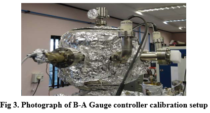
- B-A Gauge Controller Calibration Set-up
Pressure measurement in Indus Accelerator vacuum systems are performed using B-A Hot cathode Ionization Gauges. Indigenously designed B-A Gauge controllers are used for pressure measurement, process controls are used for safety of the accelerator system. The system is constructed using SS 304L hemi-spherical vacuum chamber with 8 radial ports for installation of vacuum gauges, residual gas analyser, an all metal UHV leak valve and evacuation purpose. One factory calibrated B-A gauge controller along with the controller and cable is used for reference purpose. B-A Gauge controllers are connected to other gauge heads for calibration work. Ultimate vacuum achieved is 2.0x10⁻¹¹ mbar with Sputter Ion & Titanium sublimation combination pumping. Using an all metal leak valve, pressure in the system can be varied from base vacuum to 1.0x10⁻⁵ mbar during calibration purpose with air as calibration gas. All the process parameters and their functional are routinely checked for all B-A Gauge controllers prior to installation in Indus Accelerator Vacuum Systems. Extractor Gauge system can also be added to extend calibration range down to 1x10-12 mbar in this system. The details of system is given in Figure 3.
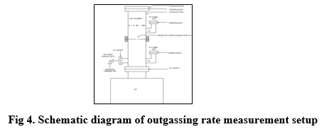
- Outgassing Rate Measurement Setup
To evaluate the outgassing rate of various materials to be used in UHV, an experimental set-up made up of all metal stainless steel (SS 304L) has been designed, developed and tested so that suitable material could be used in the electron storage rings. It is based on orifice method as per AVS standard. Sputter Ion Pump is used for achieving the ultimate vacuum of the level of 1x10⁻¹⁰ mbar and B-A Ionization Gauges are used for pressure measurement. The system is capable to withstand a bake out temperature of 2500C. Outgassing rate measurements up to ~ 5.0x10⁻¹³ mbar-l/s/cm2 are achieved using this setup. Various features of the outgassing rate measurement setup are given in Figure 4.
- UPS systems with Battery backup for
(I) Vacuum system of Indus-2 & TL-3
(II) Vacuum system of Indus-1
(III) UHV labs
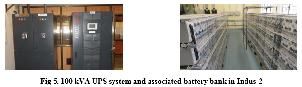
In the event of major power failure or a planned power shutdown in Indus complex, it is essential to maintain vacuum in the vacuum envelope thus keep all the SIP power supplies powered. If not done so, the vacuum recovery may take hours or days together affecting the machine operation time. Considering that the power shutdown may last for 1 working day, online 3 phase static UPS rated for 100 kVA X 2 for Indus-2 and 30 kVA for TL-3 each with 2 hour VRLA battery backup at full load have been installed. Since the UPSs feed the bus trunking system of equipment gallery, many other sub system also get benefit of conditioned uninterrupted power. Figures 5 shows one 100 kVA UPS system and associated battery bank of 800 Ah in Indus-2.
The vacuum instruments from Microtron to Indus-1 are fed by an online 3 phase static UPS system rated for 30 kVA with 2 hour battery backup at full load.
There are two UPS systems each rated for 30 kVA and with 2 hour battery backup to provide uninterrupted power required for various ongoing experiments in the UHV labs.
The UPS systems have proved to be very useful in the event of many power shutdowns or failures.
They are monitored regularly and are put under AMC for regular maintenance and reliable operation.
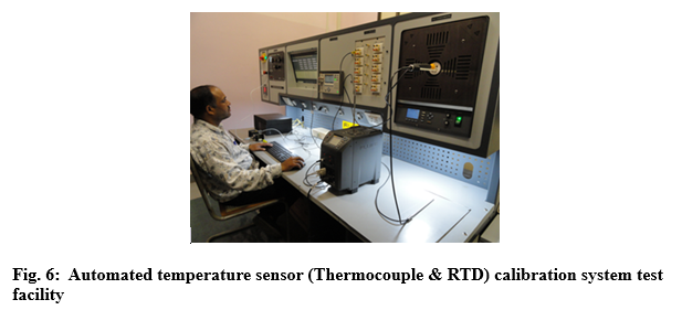
- A precise automated Dry well temperature sensor (Thermocouple & RTD) calibration system test facility
Indus machine has more than 190 Nos. of Thermocouple sensors installed on various vacuum components for monitoring the temperature during the Indus beam operation. Apart from these there are 32 nos. of thermocouples installed on Vacuum components of each vacuum segment i.e. a total of ~ 256 Thermocouple sensors, which are utilized during electrical baking operations.
Similarly, High temperature lab furnace facility in UHVTS, employ Noble thermocouple sensors (S type) & base metal Thermocouple sensors (N Type) for temperature monitoring and control.
Since these Thermocouple sensors are subjected to BR (Bremsstrahlung radiations) during Indus beam operation, a regular schedule of calibration is being followed to check the developed offsets, if any, by a precise automated Dry well temperature sensor (Thermocouple & RTD) calibration system test facility traceable to NIST standard covering the temperature range from 30 °C to 350 °C & 300 °C to 1200 °C
| Table-6.: The Salient features of the Dry well temperature sensor (Thermocouple & RTD) calibration system test facility
|
(A) 30°C to 350°C Temperature Range
- Stability:± 0.01°C
- Axial Uniformity at 40 mm (1.6 in) : ± 0.04 °C full Range
- Radial Uniformity : ± 0.01°C
- Immersion depth: 150 mm
- Well dia. : To suit insert of OD 30 mm
|
(B) 300°C to 1200°C Temperature Range
- Stability:± 0.1°C ;
- Stabilization time: 3 hours at or below 700 °C & 2 hours above 700 °C
- Axial uniformity at 60 mm max. (2.4 in): ±0.2°C for full range
- Radial Uniformity(hole to hole) : ±0.1 °C at 300 °C, ±0.20 °C at 700°C, ±0.25 °C at 1200 °C
- Immersion depth: 360 mm
- Well dia.: To suit insert of OD 35 mm
- Heater Power: 4000 W at 230 volts AC
- Heating time (25 to 1200°C): less than 45 minutes
|
Reference Thermocouple Type: Platinum Rhodium 10 % Vs. Platinum (Type S)
Accuracy (special tolerance)
- Up to 600°C ± 0.6°C
- Up to 1450°C ± 0.1% of reading
|
Precision temperature scanner: Up to 40 isolated universal inputs.
Selectable scan speed: Up to 10 channels /sec.
61/2 digit display resolution for dc voltage, dc current, and resistance
|
|
NIST traceable certificate with data at 300 °C, 700 °C, 1000 °C, and 1200 °C
|
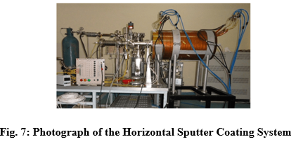
- DC Magnetron Horizontal Sputter Coating System for thin film deposition
A UHV compatible cylindrical DC magnetron horizontal sputtering system was developed for thin film deposition on inner surfaces of vacuum chamber. The system is capable of coating Titanium /NEG thin film coatings on Stainless Steel, Aluminum and ceramic vacuum chambers of different shapes upto a length of 400 mm and diameter upto of 150 mm. The salient features of the system are as follows:
- Type of sputtering method: D.C & D.C Magnetron
- Vacuum Pumping System: Turbo Molecular Pumping System for coating application and SIP system for achieving ultra high vacuum condition
- Pressure Measurement system: CDG for low vacuum and BA Gauge for UHV range
- Gas Injection System: All Metal variable leak valve with bakeable all metal Gas Reservoir and Isolation valves arrangement.
- Gases: Argon /Krypton
- Solenoid (water cooled): 300 mm (dia) x 500 mm (length)
- Magnetic Field: Variable upto 500 Gauss
- NEG thin film coating deposited on inner surface of vacuum chambers made of SS and Al alloys
- Ti coating deposited on inner surface of vacuum chambers made of high purity Alumina for pulsed Kicker magnet in Indus-2
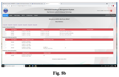
- A Bar code based tracking & maintenance management system for UHV Instrumentation in Indus facility
A bar code based tracking & maintenance management system meant for UHV Instrumentation in Indus facility digitizes & streamlines the maintenance of large numbers of power controllers of UHV Instrumentation.
The URL which was developed by computer Centre not only generates the present status, locational history, maintenance history & spare availability of the individual power controllers but also sensitizes proactively to the user of the impending calibration schedules & scheduled preventive maintenance in sync with planned Indus shutdown periods.
Data capture is done through a hand held barcode scanner capable of data editing features with a minimum of 4 numeric storing with scanned barcode capability. Data export is carried out in the form of .csv file. The Barcode scanner is equipped with keys to punch numeric and alphabets characters. The barcodes were created on the basis of the serial nos. of 80 Nos. of TSP controllers spread throughout in Indus machine & in Lab.
Similarly, testing and regular calibration of more than 190 Nos. of Thermocouple sensors installed on various vacuum components for monitoring the temperature during the Indus beam operation is also being integrated in the above maintenance management system.
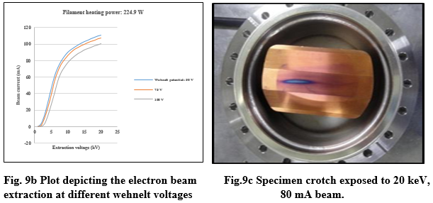
- 20 keV 2 kW DC strip type Electron gun system for photon absorber testing
Photon absorbers, also called crotches, are used to absorb unused synchrotron radiation (SR) emanating from bending magnets in synchrotron radiation sources (SRSs). In next generation SRSs, The SR power density to be absorbed by such crotches is in the range of 10-100 W/mm2. Such photon absorbers, being designed indigenously in UHVTS, need to be tested with an alternative power source simulating identical power density in vacuum environment. To meet this requirement, an electron gun based test set-up is designed and developed in UHV Lab as shown in Fig. 9a.
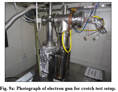
Based on the physics design of the gun by APS, mechanical design & fabrication of all the components including precision components is done by UHVTS. To meet instrumentation requirements various power supplies are installed such as 20 kV HVPS for acceleration of beam, HV deck for housing both cathode heating and Wehnelt power supplies which are floated at -20 kV, Beam current measurement & display, Vacuum pump & gauge instrumentation, Temperature monitoring on PC interface etc. The entire gun test setup is installed in a suitable radiation shielded hutch which is designed & fabricated for this purpose as per the recommendations of Health Physics Unit. The specifications of the electron gun are given in Table 1.
Table 1: Specifications of electron gun
Type of electron gun |
DC Triode (Strip Type) |
Mode of heating |
Direct heating |
Cathode material |
Pure Tungsten annealed wire dia 0.7 mm length 20 mm |
Beam foot print at the photon absorber |
(55 mm ±0.5 mm) x (2.5 mm ±0.5 mm) |
Beam energy |
20 keV |
Beam power |
2 kW max @ 100 mA ( Settable) |
Avg. power density on photon absorber |
14.5 W /mm2 |
Operating pressure |
<1E-06 mbar |
Cooling of crotch |
Chilled water cooling |
The electron beam is extracted at various cathode heating currents and wehnelt voltages as shown in Fig. 9b. At cathode heating power of 224.9 W & wehnelt voltage of 100 V, beam current of 100 mA at 20 kV(2 kW) falling on the photon absorber was measured and temperature of crotch was found to be 38 °C at 20°C chilled water flow rate of 8 lpm as shown in Fig. 9c. Radiation survey was also conducted by Health Physics Unit during the beam trials at rated beam power and radiation level was found to be close to background level inside as well as outside the hutch.